By Andy Joel
This is a sub-page of Wiring the N Gauge Layout, and focuses on the software in the Arduino.
NOTE: We are no longer using an Arduino; this page is kept for historical interest and may well disappear at some point.
What is an Arduino?
An Arduino is basically a computer. It is rather more basic than your standard computer, and has no easy way to hook up a keyboard or monitor (use a Raspberry Pi for that), but it is still a computer in that it can be programmed to do complex operations.
Here is an image.
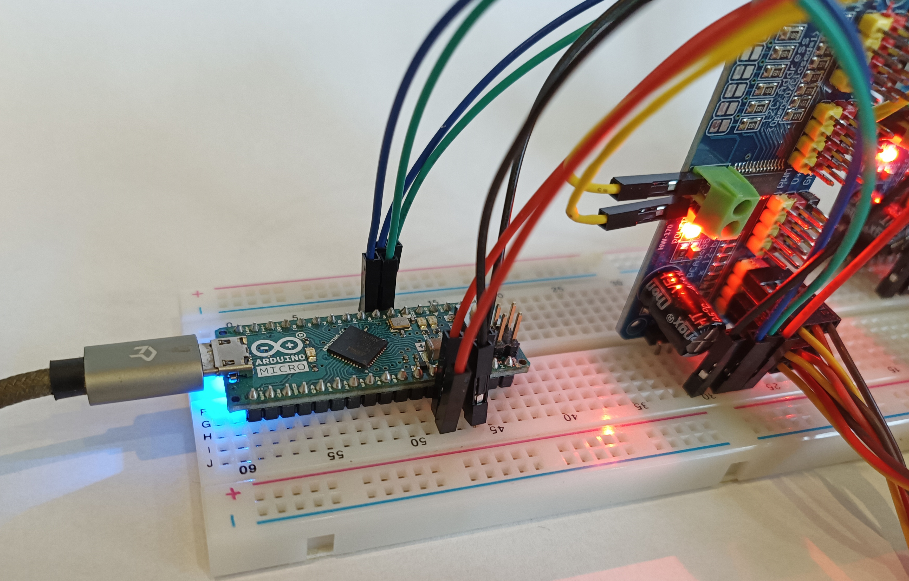
The Arduino is the board sat on the breadboard (the white block) to the left.
It has a line of pins down each side long side, and these all extend into the bread board. Each has a specific use, and is labelled as such. In the image, the red leads are connected to a 5 V supply, and the black to GND (ground), for example.
Arduinos can be programmed using software on a computer, and the cable coming out to the left is a USB connection for that purpose. You can get the software here.
Introduction To Arduino Programming
Arduinos are programming using a language called C++. I think it is actually a reduced version, but that is generally not an issue, because the reduced version has what you need.
C++ is a very common programming language that can create small and fast programs, which is probably why it was chosen.
Arduino programming is a little odd because the program is run numerous times every second. More specifically, it is the loop() method that does that, but that is the important part. You can stop the loop for a certain time using the delay() method, but that stops everything, and the Arduino will not respond to inputs during a delay, so for our purpose it is to be avoided.
Instead, we have to move things on in increments. Imagine a point needs to change, so the angle on its servo needs adjusting. The Arduino tracks what angle the servo should be at at each moment in time. In the next loop it works out where it should have got to at that moment.
Before it does that, however, it also checks to see if the user has pressed a button, and decides if it has to also react to that.
A System for Controlling Servo
For our system, then, we need to store data about each servo, some of which can change – its current angle (current_angle)and the angle it should be (target_angle). On the other hand, some will be set up in configuration will never change – its “off” position (off_angle) and it “on” position (on_angle), as well as the controller it is connected to, (cluster), and its position on that controller (number).
In the loop() method, we need to do three things:
- Determine the elapsed time.
- Check the state of every input, and react to that, modifying the target_angle of affected servos.
- Check the state of every servo (i.e., the values for the servo in the Arduino), and if the target_angle is different to the current_angle adjust the current_angle by a small increment, and then set the servo itself to that angle.
The Code
Here is version 0.3, which so far only handles inputs on the Arduino, not an I2C module. It does handle servos on multiple I2C modules, and also has an LCD connected on the I2C bus. I am breaking it up into parts to explain what is going on.
Preprocessor directives
The first part is the “preprocessor directives”; these all start with a hash. The first three lines say we want to include three libraries – one for I2C communication, one for servos, one for the LCD. The other lines set up constants. This test system has two PCA controllers and they start at address 0x40.
In theory, up to 62 PCA controllers can be connected to the I2C bus, and because of the way software is designed, it could handle that – you just need to set CONTROLLER_COUNT to the right number. Note that the addresses must be sequential for the software.
Each controller can handle up to 16 servos. Servos do not have to be connected sequentially. The means you could control up to nearly a thousand servos, but there may be an impact on performance. That said, I would guess that if you never have more than a dozen moving at the same time, it will not be noticeable.
TIME_FACTOR is a scaling factor applied to all servos, so we can adjust them all in one go. this has to be a float.
#include <Wire.h>
#include <Adafruit_PWMServoDriver.h>#
#include

#define CONTROLLER_COUNT  2
#define CONTROLLER_START  0x40
#define TIME_FACTOR 1.0

// These lines taken from example code
#define SERVOMIN  150 // This is the 'minimum' pulse length count
#define SERVOMAX  600 // This is the 'maximum' pulse length count
#define SERVO_FREQ 50 // Analog servos run at ~50 Hz updates

#define LCD_WIDTH 20
#define SKIP_DIAG_PIN 4
Global Variables
There are a number of global variables that we will use later.
Global variables are generally frowned upon in computer programs because they can be accessed – and changed – by any part of the program at any time, leading to bugs that are hard to track down. They are, however, necessary when programming Arduinos if you want data accessed both in setup() and loop(), or if you just want it to persist.
The first stores the references to the controllers, and the second to the LCD. The third is to store the time the previous loop started. All will have values assigned to them later.
Adafruit_PWMServoDriver pwms[CONTROLLER_COUNT];
LiquidCrystal_I2C lcd(0x20,LCD_WIDTH,4);
unsigned long previous_time;
They are the easy ones…
I2C Board Data
The next chunk tells the system about the I2C boards connected. The only reason to do this is so we can test they are connected for diagnostics.
Each record is stored in a struct (short for “data structure”). This is a collection of related data. I am calling it I2CBoardGroup, and saying I want there to be three values stored in it; two integers and one string.
The next part then uses I2CBoardGroup. It sets up an array called i2c_board_groups, of the type I2CBoardGroup. The next few lines then create the group of I2C boards. The first is the LCD board. It starts at address 0x20, and there is just one. The second is for the servo boards. these start at 0x40, and there is currently two of them; however, I am using the constants we set up earlier to set this up. When I add another board, I just need to change CONTROLLER_COUNT and everything else should be fine. The last line is commented out, but is for when there are I/O boards too.
struct I2CBoardGroup {
  int start_address;
  int number;
  String name;
};


I2CBoardGroup i2c_board_groups[] = {
  {0x20, 1,"LCD"},
  {CONTROLLER_START, CONTROLLER_COUNT,"Servo"},
  //{0x80, 1,"I/O board"},

};
Switch Data
The next chunk configures the switches – or more accurately links from switches to servos.
Each switch is stored in a struct again, and I am calling it SwitchData. Again there are three values stored in it; two integers and one Boolean (either true or false).
The next part then uses SwitchData. It sets up an array called switches, of the type SwitchData. The next ten lines create eight switches with the given data – this is the actual configuration. Note that the order of the data is that defined in the struct, so the first is on pin 5, modifies servo 1 to be turned on, while the second does the same but turns it off.
Note that pins 5 and 6 have two entries – they operate two servos at once. Also, the servos count from zero.
struct SwitchData {
  int pin;
  int servo;
  bool turnOn;
};

SwitchData switches[] = {
  {5, 1, true},
  {6, 1, false},
  {5, 2, true},
  {6, 2, false},
  {7, 3, true},
  {8, 3, false},
  {9, 4, true},
  {10, 4, false},
  {11, 5, true},
  {12, 5, false},
};
This will need modifying once we have I/O boards, but hopefully not too much.
Servo data
I have done this a bit differently, using a Class, rather than a struct. A Class can be thought of as a struct that also has functions as part of it. Note that functions that are part of a Class are called “methods”.
The reason for doing it this way is that I can use a special method called a “constructor” to build the servo record. The current_angle and target_angle can be set from the off_angle, making configuration easier.
This starts in a similar manner to a struct; it has seven fields, all integers.
Classes are kind of secretive; they protect their data, keeping it private. The idea is that you do not want other parts of your program making changes to values in random ways, so those seven values can only be changed by methods inside the class.
When we get to the methods, we want them accessed outside the class, so they are flagged as public.
Then it gets complicated, as we define a number of methods: Servo(), set(), adjust(), update() and status(). And really, all the hard work is being done here.
class Servo {
  int cluster;  // 0 - 5 or so
  int number; // 0 - 15
  int speed;
  int target_angle;
  int current_angle;
  int off_angle;
  int on_angle;

  public:
  Servo(int _cluster, int _number, int _speed, int _off_angle, int _on_angle) {
    cluster = _cluster;
    number = _number;
    speed = _speed;
    off_angle = _off_angle * 100;
    target_angle = _off_angle * 100;
    current_angle = _off_angle * 100;
    on_angle = _on_angle * 100;
  }

  void set(bool turnOn) {
    target_angle = turnOn ? on_angle : off_angle;
  }

  bool adjust(float elapsed) {
    int diff = current_angle - target_angle;
    if (diff == 0) return false;

    int increment = elapsed * speed;
    // diff is then capped at that
    if (diff > 0) {
      if (diff > increment) diff = increment;  // cap at speed
      current_angle -= diff;
    }
    else {
      if (diff < increment) diff = increment;  // cap at speed
      current_angle += diff;
    }
    update();
    return true;
  }

  void update() {
    int pulselen = current_angle * (SERVOMAX - SERVOMIN) / 18000 + SERVOMIN;
    if (pulselen > SERVOMAX) {
      Serial.print("ERROR: Too high!!!");
      return;
    }
    if (pulselen < SERVOMIN) {
      Serial.print("ERROR: Too low!!!");
      return;
    }
    pwms[cluster].setPWM(number, 0, pulselen);
  }

  String status() {
    return String(current_angle) + "/" + String(target_angle);
  }

};
We better look at these in detail…
The first method has the same name as the class; this is the “constructor”, and is used when an instance of the class is created. The first line says we expect to be given five values. The internal variables are set from these.
Internally angles are stored as hundreds of a degree. I could have done this with a float, but I prefer to work with integers!
This does mean that if the speed is so low that it should move by less than one hundredth of a degree in one cycle, it will never move. That could be rectified by making it always move at least 1, or using smaller divisions, or both?
Servo(int _cluster, int _number, int _speed, int _off_angle, int _on_angle) {
    cluster = _cluster;
    number = _number;
    speed = _speed;
    off_angle = _off_angle * 100;
    target_angle = _off_angle * 100;
    current_angle = _off_angle * 100;
    on_angle = _on_angle * 100;
  }
The set() method sets the servo in response to a button being pressed. More specifically, it sets the target_angle – the angle we want the servo to move to. It is passed a Boolean value indicating if we want to move to the “on” position or not.
  void set(bool turnOn) {
    target_angle = turnOn ? on_angle : off_angle;
  }
The adjust() method will be run every loop, and decides if the current_angle needs to be adjusted, and if so by how much. It is passed the time that has passed since the last loop. After changing current_angle it calls update().
  bool adjust(float elapsed) {
    int diff = current_angle - target_angle;
    if (diff == 0) return false;

    int increment = elapsed * speed;
    // diff is then capped at that
    if (diff > 0) {
      if (diff > increment) diff = increment;  // cap at speed
      current_angle -= diff;
    }
    else {
      if (diff < increment) diff = increment;  // cap at speed
      current_angle += diff;
    }
    update();
    return true;
  }
The update() method is the only one that communicates with the actual servo. It updates the angle of the servo with current_angle.
void update() {
    int pulselen = current_angle * (SERVOMAX - SERVOMIN) / 18000 + SERVOMIN;
    if (pulselen > SERVOMAX) {
      Serial.print("ERROR: Too high!!!");
      return;
    }
    if (pulselen < SERVOMIN) {
      Serial.print("ERROR: Too low!!!");
      return;
    }
    pwms[cluster].setPWM(number, 0, pulselen);
  }
Finally, the status() method is used only for debugging – it returns a string with the current_angle and the target_angle.
  String status() {
    return String(current_angle) + "/" + String(target_angle);
  }
Now each servo is configured. The first one in on controller 0, in position 0. Its speed is 1. Its “off” angle is 0, and its “on” angle is 180. Angles are specified in degrees here, but converted to hundredths of a degree in the constructor. It does not matter if the “off” angle is greater; they can be either way round.
Servo servos[] = {
  Servo(0, 0, 1, 0, 180),
  Servo(0, 1, 3, 10, 120),
  Servo(0, 3, 1, 0, 90),
  Servo(1, 1, 1, 0, 180),
  Servo(1, 2, 4, 0, 180),
  Servo(1, 3, 4, 0, 90),
};
More Globals
A couple more globals are then set up. We have to do them last because they are the size of the arrays and it is best to let the program work out the size – if we add another servo to the list, the number will still be right.
The last two are used for diagostics.
const int servo_count = sizeof(servos)/sizeof(servos[0]);
const int switch_count = sizeof(switches)/sizeof(switches[0]);
bool moving_flag = false;
bool diag_flag = false;
Custom Functions
I have a custom to write to the LCD. This is something that is done in various points in the code, and is not straightforward, so is best done in its own code block.
It accepts a string, which it truncates or pads to exactly 20 characters, LCD_WIDTH, before sending to the display.
There is a second custom function that gets diagostic information and puts it on the LCD (using print_line). The diagnostocs seems to slow the Arduino down significantly, so can be turned off, and if it is, we want to blank those lines on the LCD this loop, then skip altogether thereafter. The first ten lines deal with that. The middle chunk checks communication with each I2C module. The last chunk sends results to the LCD.
void diagnostics(int elapsed)
{

  if (digitalRead(SKIP_DIAG_PIN) == HIGH) {
    if (!diag_flag) {
      print_line(1, "Diagnostics off");
      print_line(2, "");
      print_line(3, "");
    }
    return;
  }
  diag_flag = false;

  print_line(1, moving_flag ? "Servo moving" : "");

  String result = "";
  for (int i = 0; i < sizeof(i2c_board_groups)/sizeof(i2c_board_groups[0]); i++) {
    for (int j = 0; j < i2c_board_groups[i].number; j++) {
      int address = i2c_board_groups[i].start_address + j;
      Wire.beginTransmission(address);
      int error = Wire.endTransmission();
      if (error != 0) {
        result += " ";
        result += String(address);
      }
    }
  }
  print_line(2, result == "" ? "All I2C connected" : ("No I2C:" + result));


  String s = "Lp ";
  if (elapsed < 100) s += " ";
  s += String(elapsed);
  s += "ms Up ";
  s += String(millis() / 1000);
  s += "s";
  print_line(3, s);
}
Arduino Functions
There are two functions all Arduino code needs.
setup()
The setup() function is run once, when the Arduino is turned on.
The I2C interface is initialised.
The serial interface with the computer is set up – this is useful for diagnostics during development.
The next three lines set up the input pins. This is done in a loop, where i is a counter. Note that arrays count from zero in C++ (in common with most other languages). The mode for each pin is set to INPUT_PULLUP, which is a built-in constant.
The next five lines initialise the LCD.
Then a pin is set that we can use to turn diagnostics on and off.
The next six lines set up communication with the PCA controllers. Again, this is done in a loop, with i being the count. The actual initialisation is pretty much copied from an example program.
Then another loop, going through each servo, and setting it to the “off” position, so the servos are all in the same state as the software thinks it is.
Then we record the time.
void setup() {
  Wire.begin();

  Serial.begin(9600);

  for (int i = 0; i < switch_count; i++) {
    pinMode(switches[i].pin, INPUT_PULLUP);      // set pin to input
  }

  lcd.init();
  lcd.backlight();
  lcd.home();
  lcd.setCursor(0, 0);
  lcd.print("Preston&District MRS");

  pinMode(SKIP_DIAG_PIN, INPUT_PULLUP);

  for (int i = 0; i < CONTROLLER_COUNT; i++) {
    pwms[i] = Adafruit_PWMServoDriver(CONTROLLER_START + i);
    pwms[i].begin();
    pwms[i].setOscillatorFrequency(27000000);
    pwms[i].setPWMFreq(SERVO_FREQ);
  }

  for (int i = 0; i < servo_count; i++) {
    servos[i].update();
  }

  previous_time = millis();
}
loop()
The loop() function is where the action happens. This is repeated hundreds of times every second.
loop: Handling time
This is complicated because of the types of numbers involved…
In the Arduino a standard integer can have a value from -32,768 to 32,767. A long integer, however, has twice the storage space, and can be from -2,147,483,648 to 2,147,483,647. The millis() function returns the number of milliseconds since the unit was turned on as an unsigned long integer, which can range from 0 to 4,294,967,295.
void loop() {
  // HANDLE TIME
  unsigned long now_time = millis();
  unsigned long elapsed = now_time - previous_time;
  previous_time = now_time;
  int increment = TIME_FACTOR * elapsed;

  // HANDLE DIAGNOSTICS
  diagnostics(elapsed);
However, in practice the elapsed time is only going to be a few milliseconds, so we are safe pushing that into an int. The TIME_FACTOR constant allows us to slow down or speed up all servos in one change.
The diagnostics function discussed earlier is then called.
loop: Handling Inputs
We go though each switch, and see if it is in the LOW state. We set them earlier to use a pull-up resistor, so LOW indicates the switch is closed.
If it is, we use the set() method of the relevant servo to change its target angle.
  // HANDLE INPUTS
  for (int i = 0; i < switch_count; i++) {
    if (digitalRead(switches[i].pin) == LOW) {
      int servo_no = switches[i].servo;
      if ((servo_no < 0) || (servo_no >= servo_count)) {
        Serial.println("Bad servo number: " + String(servo_no));
        continue;
      }
      servos[servo_no].set(switches[i].turnOn);
      Serial.println("switch:" + String(i) + "servo:" + String(servo_no) + " (" + servos[servo_no].status() + ")");
      //Serial.println("servo_count:" + String(servo_count) + " (" + String(i) + ")");
    }
  }
It does check servo_no is in range. C++ does no checking itself, and this is part of the configuration, so important, though arguable should be done in setup()!
Note that holding down the button will do no harm; you are just repeatedly setting a target_angle. In fact, holding down both the left and the right buttons at the same time will not cause any issues; target_angle will flip back and forth, but we are not adjust the actual servo yet, so whichever switch is later in the list will “win” and the servo will move towards that.
loop: Handling Outputs
Again we have a loop, with i as the counter, but now we are going through every servo. All the hard work is done in the class method adjust().
  moving_flag = false;
  for (int i = 0; i < servo_count; i++) {
    if (servos[i].adjust(increment)) moving_flag = true;
  }
All Together Now…
The full code is here:
// Servo control via I2C bus version 0.3
// Copyright Andy Joel and Preston&District Model Railway Club
// Documentation here:
// http://www.prestonanddistrictmrs.org.uk/articles/point-control-with-servos/coding-the-arduino-for-the-n-gauge-layout/

#include
#include
#include


#define CONTROLLER_COUNT  2
#define CONTROLLER_START  0x40
#define TIME_FACTOR 1.0

#define SERVOMIN  150 // This is the 'minimum' pulse length count (out of 4096)
#define SERVOMAX  600 // This is the 'maximum' pulse length count (out of 4096)
#define SERVO_FREQ 50 // Analog servos run at ~50 Hz updates

#define LCD_WIDTH 20
#define SKIP_DIAG_PIN 4

Adafruit_PWMServoDriver pwms[CONTROLLER_COUNT];
LiquidCrystal_I2C lcd(0x20,LCD_WIDTH,4);  // set the LCD address to 0x27 for a 20 chars and 4 line display
unsigned long previous_time;


struct I2CBoardGroup {
  int start_address;
  int number;
  String name;
};


I2CBoardGroup i2c_board_groups[] = {
  {0x20, 1,"LCD"},
  {CONTROLLER_START, CONTROLLER_COUNT,"Servo"},
  //{0x20, 1,"LCD display"},

};


struct SwitchData {
  int pin;      // the pin the switch is on
  int servo;    // Number of the sefvo in the list servo_configs below
                // Note that they count from zero!
  bool turnOn;  // If true, will set the servo to the "on" position
};

SwitchData switches[] = {
  {5, 1, true},
  {6, 1, false},
  {5, 2, true},
  {6, 2, false},
  {7, 3, true},
  {8, 3, false},
  {9, 4, true},
  {10, 4, false},
  {11, 5, true},
  {12, 5, false},
};


class Servo {
  int cluster;  // 0 - 5 or so
  int number; // 0 - 15
  int speed;
  int target_angle;
  int current_angle;
  int off_angle;
  int on_angle;

  public:
	Servo(int _cluster, int _number, int _speed, int _off_angle, int _on_angle) {
    cluster = _cluster;
    number = _number;
    speed = _speed;
    off_angle = _off_angle * 100;
    target_angle = _off_angle * 100;
    current_angle = _off_angle * 100;
    on_angle = _on_angle * 100;
  }

  void set(bool turnOn) {
    target_angle = turnOn ? on_angle : off_angle;
    //Serial.print(String(turnOn) + " ");
  }

  bool adjust(float elapsed) {
    int diff = current_angle - target_angle;
    if (diff == 0) return false;

    int increment = elapsed * speed;
    // diff is then capped at that
    if (diff > 0) {
      if (diff > increment) diff = increment;  // cap at speed
      current_angle -= diff;
    }
    else {
      if (diff < increment) diff = increment; // cap at speed current_angle += diff; } update(); return true; } void update() { int pulselen = current_angle * (SERVOMAX - SERVOMIN) / 18000 + SERVOMIN; if (pulselen > SERVOMAX) {
      Serial.print("ERROR: Too high!!!");
      return;
    }
    if (pulselen < SERVOMIN) {
      Serial.print("ERROR: Too low!!!");
      return;
    }
    pwms[cluster].setPWM(number, 0, pulselen);
  }

  String status() {
    return String(current_angle) + "/" + String(target_angle);
  }
};


Servo servos[] = {
  Servo(0, 0, 1, 0, 180),
  Servo(0, 1, 3, 10, 120), // this one does not like to go beyond 120deg!
  Servo(0, 3, 1, 0, 90),
  Servo(1, 1, 1, 0, 180),
  Servo(1, 2, 4, 180, 0),
  Servo(1, 3, 4, 0, 30),
};


const int servo_count = sizeof(servos)/sizeof(servos[0]);
const int switch_count = sizeof(switches)/sizeof(switches[0]);
bool moving_flag = false;
bool diag_flag = false;


void print_line(int line, String str) {
    lcd.setCursor(0, line);
    str = str.substring(0, LCD_WIDTH);
    for (int i = str.length(); i < LCD_WIDTH; i++) str += ' ';
    lcd.print(str);
}


void diagnostics(int elapsed)
{

  if (digitalRead(SKIP_DIAG_PIN) == HIGH) {
    if (!diag_flag) {
      print_line(1, "Diagnostics off");
      print_line(2, "");
      print_line(3, "");
    }
    return;
  }
  diag_flag = false;


  print_line(1, moving_flag ? "Servo moving" : "");


  String result = "";
  for (int i = 0; i < sizeof(i2c_board_groups)/sizeof(i2c_board_groups[0]); i++) {
    for (int j = 0; j < i2c_board_groups[i].number; j++) {
      int address = i2c_board_groups[i].start_address + j;
      Wire.beginTransmission(address);
      int error = Wire.endTransmission();
      if (error != 0) {
        result += " ";
        result += String(address);
      }
    }
  }
  print_line(2, result == "" ? "All I2C connected" : ("No I2C:" + result));


  String s = "Lp ";
  if (elapsed < 100) s += " ";
  s += String(elapsed);
  s += "ms Up ";
  s += String(millis() / 1000);
  s += "s";
  print_line(3, s);
}


void setup() {
  Wire.begin();

  Serial.begin(9600);

  lcd.init();                      // initialize the lcd
  lcd.backlight();
  lcd.home();
  lcd.setCursor(0, 0);
  lcd.print("Preston&District MRS");
  pinMode(SKIP_DIAG_PIN, INPUT_PULLUP);           // set pin to input

  for (int i = 0; i < switch_count; i++) {
    pinMode(switches[i].pin, INPUT_PULLUP);           // set pin to input
  }

  for (int i = 0; i < CONTROLLER_COUNT; i++) {
    pwms[i] = Adafruit_PWMServoDriver(CONTROLLER_START + i);
    pwms[i].begin();
    pwms[i].setOscillatorFrequency(27000000);
    pwms[i].setPWMFreq(SERVO_FREQ);  // Analog servos run at ~50 Hz updates
  }

  Serial.println("Checking servo configuration...");
  for (int i = 0; i < switch_count; i++) {
    int servo_no = switches[i].servo;
    if ((servo_no < 0) || (servo_no >= servo_count)) {
      Serial.println("Bad servo number: " + String(servo_no));
    }
  }
  Serial.println("Done");

  for (int i = 0; i < servo_count; i++) {
    servos[i].update();
  }


  //while (!Serial); // wait for output to fire up before sending. But what if it is not connected???
  //Serial.println("Found " + String(servo_count) + " servos!");  // does not appear
  previous_time = millis();
}


void loop() {
  // HANDLE TIME
  unsigned long now_time = millis();
  unsigned long elapsed = now_time - previous_time;
  previous_time = now_time;
  float increment = TIME_FACTOR * elapsed;


  // HANDLE DIAGNOSTICS
  diagnostics(elapsed);


  // HANDLE INPUTS
  for (int i = 0; i < switch_count; i++) {
    if (digitalRead(switches[i].pin) == LOW) {
      int servo_no = switches[i].servo;
      if ((servo_no < 0) || (servo_no >= servo_count)) {
        Serial.println("Bad servo number: " + String(servo_no));
        continue;
      }
      servos[servo_no].set(switches[i].turnOn);
      Serial.println("switch:" + String(i) + "servo:" + String(servo_no) + " (" + servos[servo_no].status() + ")");
      //Serial.println("servo_count:" + String(servo_count) + " (" + String(i) + ")");
    }
  }


  // HANDLE SERVOS
  moving_flag = false;
  for (int i = 0; i < servo_count; i++) {
    if (servos[i].adjust(increment)) moving_flag = true;
  }

}