By Andy Joel
This page aims to document the wiring for the club’s new N gauge layout. The long term purpose is to provide a record of what we did and why, so the layout can be maintained into the future even if those who built it are no longer at the club.
Design Constraints
The layout will be used for: (1) members to run trains at the club; and (2) taking to exhibitions.
The layout is split into four boards. Connections will be required between them, but we would want to keep that to a minimum.
The lower level is to be DCC only.
The upper level, two independent circuits, will be swappable between DC and DCC. Can we consider some degree of automation for the upper circuit at exhibition?
It has to be relatively easy to diagnose and fix problems.
Track Wiring
Currently only the track on the lower level is in place, and so that is being wired.
As it is DCC, the track is all connected, all the time. Every section of track is connected to a bus under the board. The rail of each section of track is joined to the blue bus wire – and joined using blue wires. The outer rail is joined to the brown.
The image below is of the far left corner of the layout, with the two thicker wires of the DCC bus visible at the bottom, with various smaller wires to the track sections.
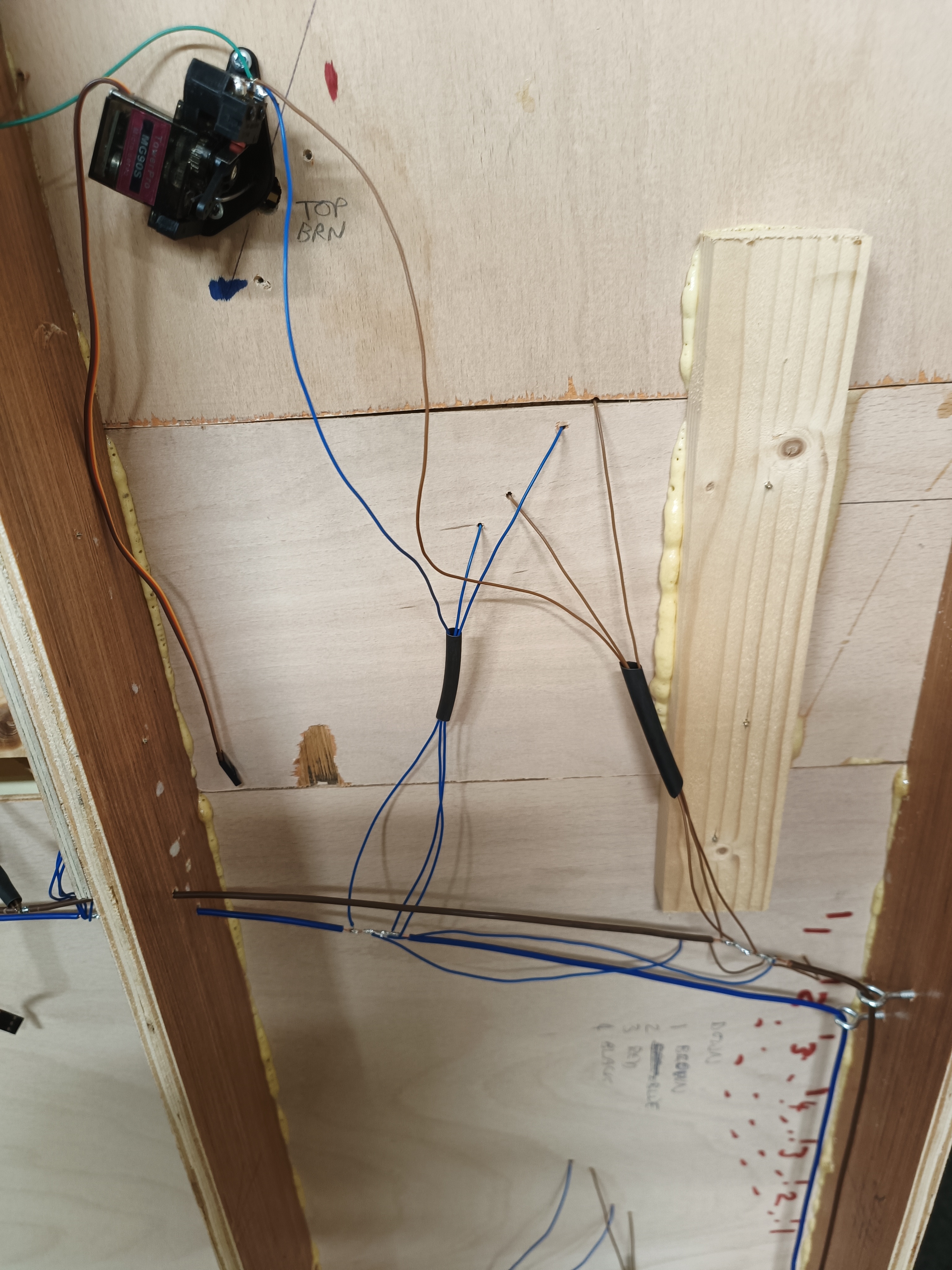
At the top is a servo for a point. This has a green wire passing to the left of the image connected to the point frog. This needs to be connected to either the blue of the brown, depending on how the point is set, so is joined to the common pole of a microswitch. The other two poles of the switch are connected to the brown and blue.
We used a multimeter to determine which way round the brown and blue had to go!
It does get more complicated when more points are present. This is the view to the left on the one above, and shows five connected points (and two not connected for the upper level). Blue and brown connectors jump from one switch to the next to try to reduce the wires present.
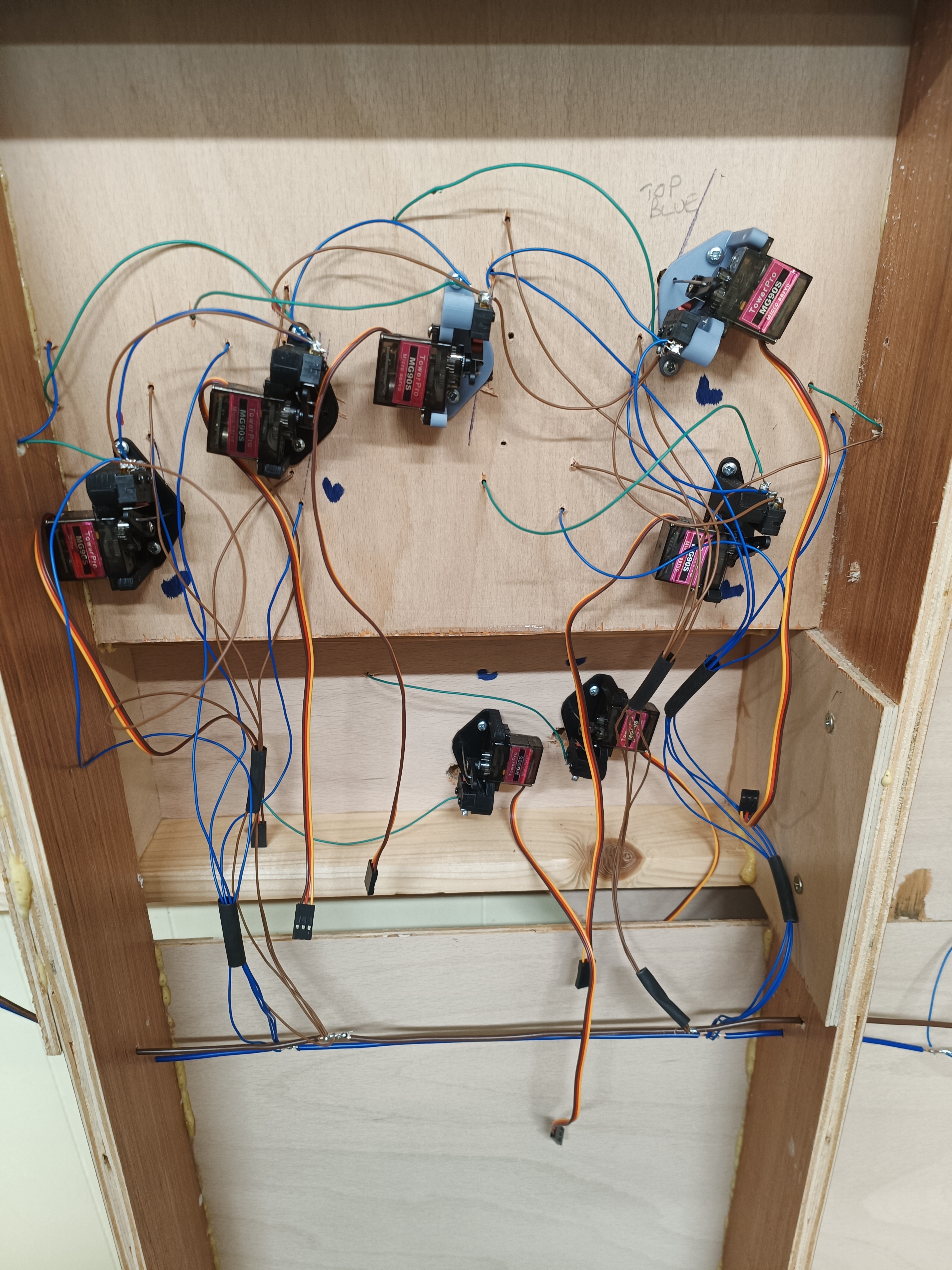
The yellow/red/black wires dangling from each point is for the servo that moves it. And that brings us to…
Point Control With Servos
There are various ways to control points on a model railway layout, so why use servos?
Servos can be set to move slowly, giving a more realistic action, are hopefully quieter and are considerably cheaper. If you buy several at a time, you can get them for as little as £2 each. That said, you do also need to buy controllers, but one controller will handle several servos, and using controllers significantly reduces the wiring between boards – you just need five wires between the controllers, rather than two for every point.
The down side is that there is a fair bit of configuration. Servos are general purpose; they are not built for points on model railways, and so have to be set up just right. You also need software to run them, and there are various approaches to that available.
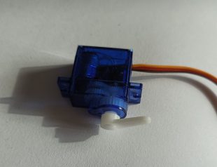
The Servo
A servo is a device that will rotate its arm to a given angle, usually within a span of 180 degrees. An electronic signal is sent to it to set the angle. This uses pulse width modulation (PWM). The servo has three wires connected, one being power, one being ground and the third being the signal. Messages are sent down the signal line in the form of pulses – the longer the pulse, the greater the angle the servo will adopt.
If the servo is set to 89 degrees, and is set a signal corresponding to 42 degrees, it will quickly adjust its angle. If the 42 degree signal continues to be sent, it will do nothing, as it is already at that angle (it is generally best to only send a signal when you want it to move, if you continuously send it the same signal you can get buzzing, I think because noise on the line can make it move just slightly all the time).
There is no inherent way to alter the speed of the servo, but a controller can tell it to change in increments, effectively slowing it down.
Fitting to a Point
There are various approaches to this. Note that you need some flexibility in the connection to allow the servo to go slightly beyond the start and end. You also need to allow for thermal expansion. It is usual, therefore to use piano wire, with the servo causing the wire to pivot, rather than move lengthways.
The method we have adopted has the axis of the servo parallel to the direction of running. In the image below, the flat plate on the right will be attached to the board, with the wire extending through the board to the point. The servo moves the arm below the servo, the wire pivots at the hole. This allows for a significant movement in the servo, for the 1-2 mm movement in the point.
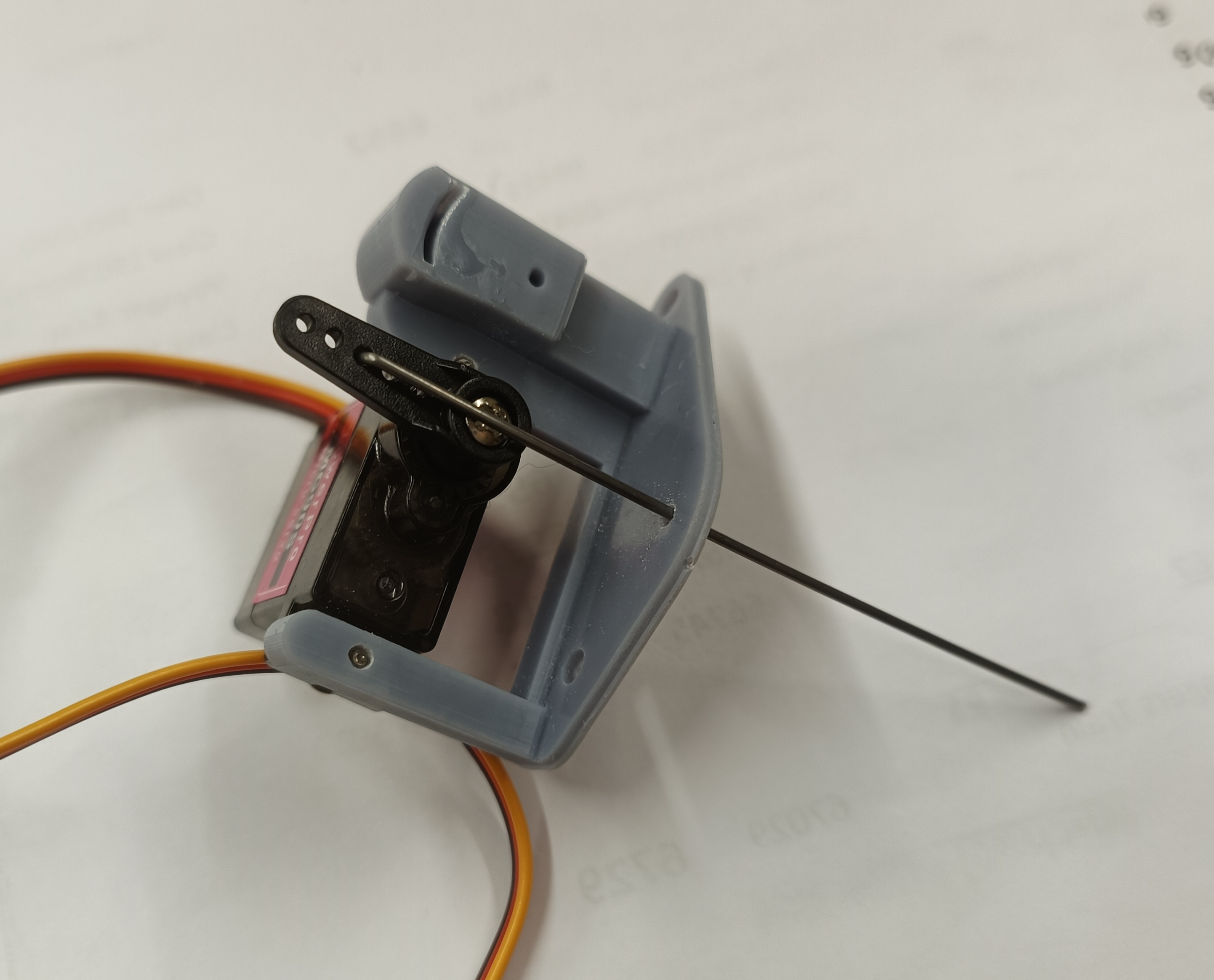
In addition, a microswitch is fitted to switch the power to the point. the image below shows the unit with the microswitch fitted on the right. This is, to my mind, the tricky bit as the switch has to change whilst the point blades are between the rails – otherwise a short circuit will occur.
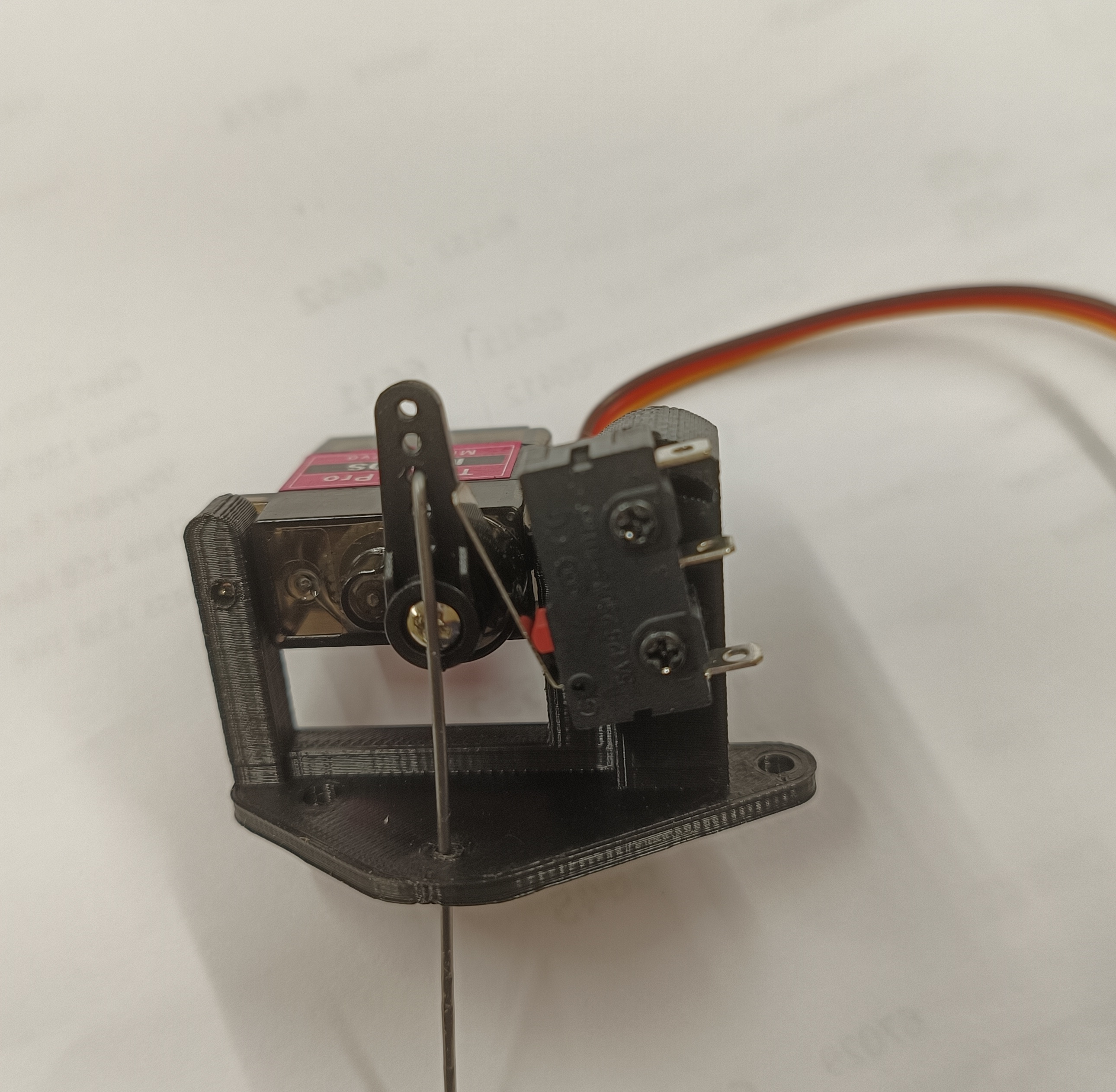
The fitting is 3d printed. Experience has shown it needs to be pretty strong, and standard resin prints are not up to the job, breaking when screwing into them (hence we abandoned the grey, and now use the black).
Wiring
Each cluster of points is controlled by a board with a PCA9685 chip. These boards are about £4, and each can control up to 16 servos.
A manual is available here.
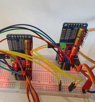
The image above shows two such controllers on a breadboard during development. Servos are plugged in on the right of each board; these both have three plugged in – the black sockets at the bottom. The pins are colour-coded the same as the servos.
On the left side, towards the top, there are pairs of metal squares; these are connected to give the address. The unit on the right has the very top pair connected, so is at 0x41, the left is at the default address 0x40 (the 0x prefix indicates this is a hexadecimal number).
Each controller needs a 5V supply, and this is supplied via the green connectors halfway up the left side. The documentation suggests this is “polarity neutral”, but I found that if you do it the wrong way round, you get no voltage; I guess something is shorted. Positive needs to be to the lower connection.
Control Bus
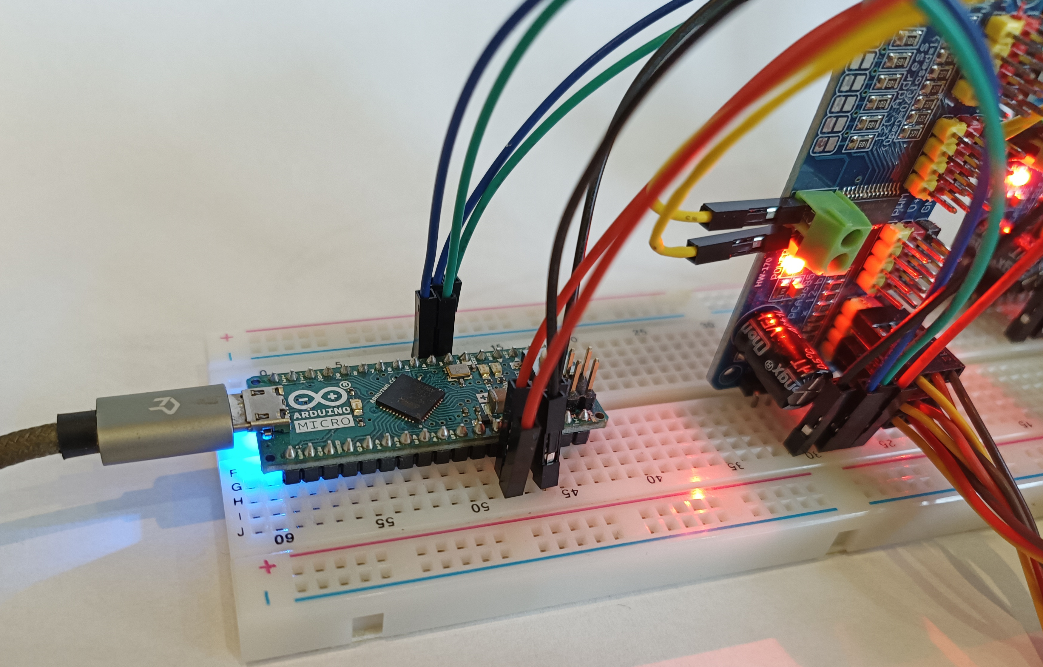
The controllers in the image above were connected to an Arduino using a protocol called I2C, which is technology from the 80s but seems popular still (more here). The Arduino has now been abandoned in favour of a Raspberry Pi but still using I2C, so the discussion here is not changed. The Raspberry Pi is much faster, and can be programmed with Python, rather than C++, which is a big plus for me!
The bus consists of four wires, two being power, one for clock (SCL) and one for the data (SDA). This is in addition to the power for the servos.
An independent supply is required. It can share a ground wire with the I2C bus, but it has to be connected to both the power ground and the I2C ground at each end.
The Raspberry Pi requires an uninterruptible power supply (UPS) to turn it off gracefully when the layout is unplugged. This has yet to be implemented.
Pullup Resistors
Imagine a simple system. Our digital processor wants to know if it is at 0 V or at 5 v. Simplistically, you would have a switch on the 5 V line; when the switch in on, the output is 5 V, and all is good. In practice it is not as straightforward. When the switch is off, the output is… what? It is not connect to ground, so no reason for it to be 0 V.
So pullup resistors (or pull down in the reverse configuration) are used. Now the output is connect to the 5 V supply via a resistor, and to the 0 V ground by the switch. When the switch is on, the output is connected to ground, and is 0 V. When it is off, the output is still connected to the 5 V supply, albeit via the resistor.
The I2C data lines both require pullup resistors. Most devices have them built-in, though not the Arduino, so no problem, right? Well that works find for one or two devices, and if you have several, all those resistors are in parallel, and the overall resistance is reduced – if you have ten identical pullup resistors in the circuit, the resistance is only a tenth of what it should be.
I am not sure what to do about that if it proves to be an issue. It may be possible to disable pullup resistors on some boards. It may also be possible to have more than one I2C bus, but I really would prefer not to!
Presumably the resistance can be measured with a multimeter, and we can monitor as we add units.
Programming The Raspberry Pi
The hard work is done in a Raspberry Pi. This will require programming, and a page on that is on Github. You can find the code there too, as well as instructions for setting up a new Raspberry Pi.
Control Panel
We need some way for operators to control the points.
From the perspective of the Raspberry Pi, I see two approaches.
- “Continuous” A switch is set to allow current to pass while the point is set in that direction. At any moment, the Raspberry Pi can test the state of the switch, and react accordingly. The switch is definitive – the current state of the switch defines what the point should be doing. The advantage of this is that operators can just look at the switch to see the state, and the controller can test the switches when it is turned on to determine point state. A selector switch could be used rather than simple on/off.
- “Momentary” A switch or button allows current to pass for a moment, informing the controller a point is to be changed. The controller is definitive, not the switch. The advantage is that you can have more than one button controlling a specific point, allowing you to have buttons setting a route, not just one point. You could even interface with a touch-screen monitor.
I think I prefer the latter, and will go with that during development, but it is not set in stone. Yet.
This would be via the I2C bus too, as this allows many more inputs via an I/O board.