By Andy Joel
Overhead Line electrification (OLE) is a common sight across the railways of the UK, and hence something that is often modelled. It is a big feature of our own Euxton Junction layout, and will also be present on the new N gauge layout currently under construction.
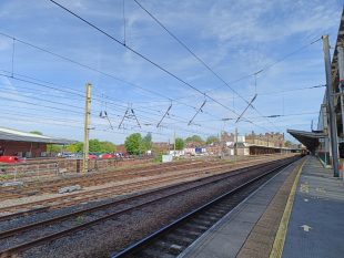
All images are from Preston Station and the lines just to the north of it.

Introduction
The most common electrification system on the railways of Britain – and I think across the world – is 25kV AC taken from overhead wires. A lot of early schemes used lower voltages and a DC supply, including the Woodhead line, which was 1500 V DC, and often a third, or even fourth rail was used. Third and fourth rail systems are still in use in the UK, but due to the inherent dangers I do not think they can be extended except in unusual circumstances.
The advantage of AC is that it can be transformed between different voltages readily, however, it was not until the early sixties when the technology to rectify the electricity in the loco became available, that AC electrification took off. Some earlier AC systems used 6.25 kV, and I think some trains out of Liverpool Street were dual voltage to cope with both.
West Coast Main Line
As a resident of Preston, this is the electrification that interests me!
The West Coast Main Line (WCML) was electrified from 1960 onwards, with Crewe to Manchester electrified in 1960, reaching Liverpool in 1962, and London, Euston in 1965. Electrification all the way to Glasgow – including Preston – was completed in 1974.
The Wires
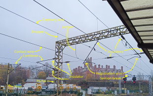
The catenary is made up of various parts. The copper wire the pantograph touches is called the contact wire, and is between 4.165 m to 5.94 m from the rail, generally lower as it goes under bridges and higher over level crossings. Early electrification schemes (pre-WW2) often had the wires higher than that through stations.
Rather than lie directly over the centre of the track, it also zig-zags to avoid excessive wear on one part of the pantograph, up to 230 mm off-centre on straight sections, and up to 380 on curves. The contact wire is held is place with a registration arm, which is horizontal, and perpendicular to the track. This pushes or pulls the contact wire to give the zigzag, and must be under quite a bit of strain along its length given the pull on the wire to keep a taut, but is free to move in the direction of the track to some degree to allow for movement of the contact wire as it expands and contracts.
If you were to simply string a single cable between each mast (as on some tramway systems), they will be a lot of play in the middle of the span, and hardly any at the masts. To combat this, the contact wire is hung from the messenger or catenary wire by droppers. I guess the catenary wire is steel for strength. This is 1800 mm above the contact wire (900 mm on more modern mark 3 catenary) at the masts, generally drooping to no less than 400 mm in the middle of a span, though it can be less to pass under bridges (see the image in Supports, below).
Some systems, known as “compound” rather than “simple”, have a third wire between these, the auxiliary wire. This seems to be the case for the first stage of the WCML; Manchester/Liverpool to Euston. By the time the north section was electrified, they had decided it was not necessary.
There are also jumper cables to ensure both wires are at exactly the same voltage.
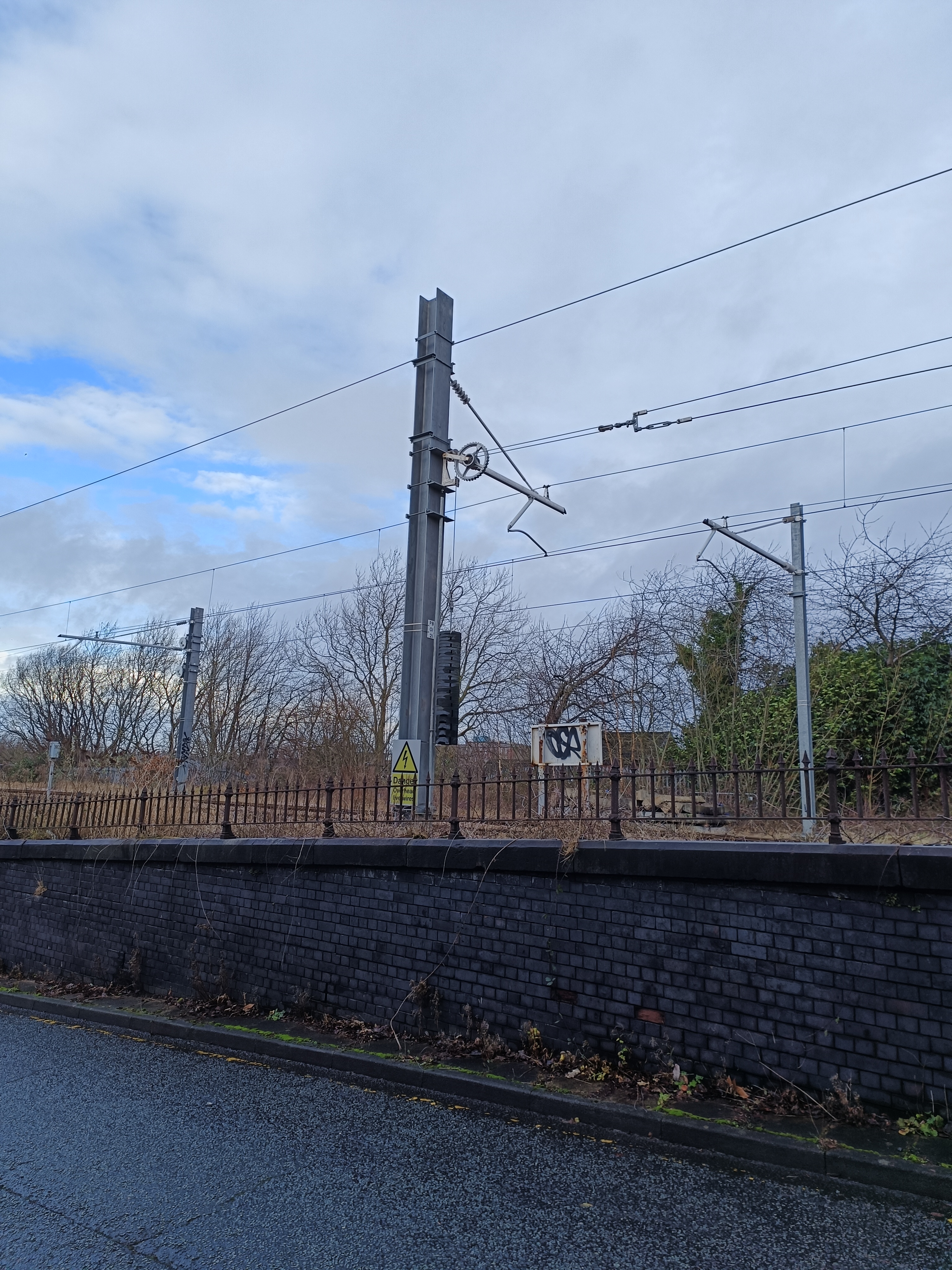
The contact wire is kept under tension, which is achieved by hanging weights off the end of it, as you can see in the image below. I think for modern installations this is done with springs inside disc-shaped boxed.

The Supports
The wires are held up by masts, which are spaced between 13 m and 73 m, with shorter spans used as required, for example areas with strong side winds, and as dictated by infrastructure such as bridges.
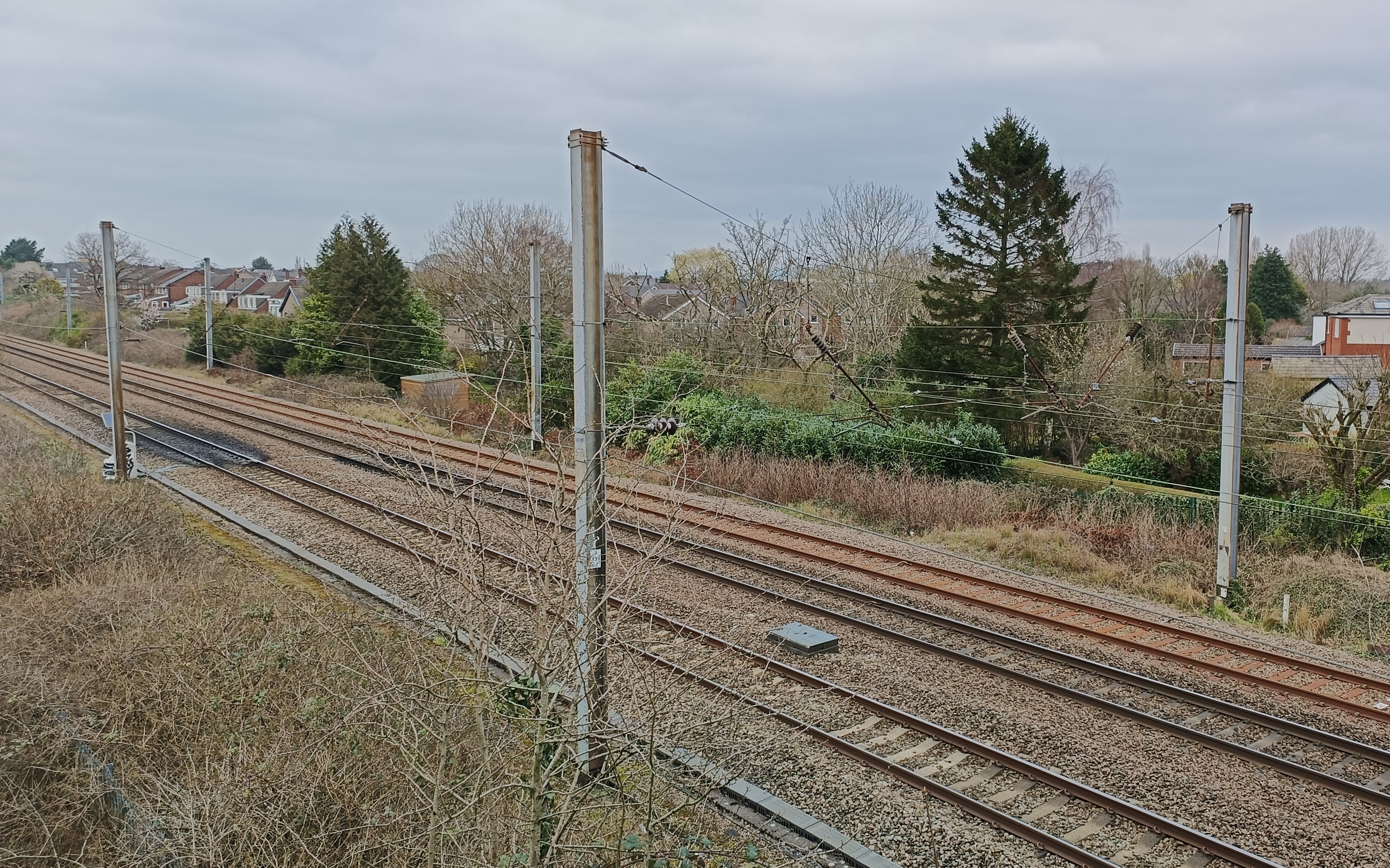
There are a lot of designs, even in the same area, as the images on this page show. The simplest is the cantilever and post, and is common for double track. The post is usually an H section, about 200 mm across.

This image shows a more modern version, on the line to Blackpool, and would have been put in place around 2017.

The annotated image earlier shows an example of a cantilever on the side of another support, a portal.
A portal goes right across the track, with the wires hung from it. There are various designs and the one in the annotated image seems most common, but here is another.

Some portals have the mast on one side only – I assume because of space constraints.
A headspan is similar to a portal, but using wires to span the tracks, and is especially common where there are multiple tracks.
Curiously, they do not always have posts on both side. This is on the west side of Preston station. It give no support, but I guess does adjust the lateral position over what may be a relatively tight radius.

Insulators
While the wires are at 25 kV, the masts are at 0 V, and clearly there can be no connectivity between the two. To this end, all supports are fitted with insulators. Back in the day there were porcelain, but are polymer nowadays, as seen in the annotated image above. They have a strange nobbily shape to prevent electricity arcing across them in wet conditions.
The image below is a virtual representation indicating the shape; the polymer version on the left, porcelain on the right.

Supply
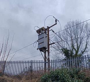
The image at the top shows a point where electricity is supplied to the overhead line. the brick building is, I guess, a substation, though further electric equipment is visible to the left of it. The supply seems to pass through a light grey box on the back of the mast, which looks to be oil-cooled. The supply the passes up the back of the mast, over the insulators at the top, presumably just to keep it way from anything else. the supply for the near track crosses the tracks on a wire suspended high up between the masts.
Sections
The electrification is split into sections in part to allow for supply from different sources and also so a section can be isolated for maintenance. A section break can be seen in the annotated image above, and I think the box in the image below is for isoalting (but it could be a transformer for supply),
End of the Line
The end of electrification is just where the wires meet insulators.

I am not aware of anywhere where the tension is provided at the terminating point. That might be a safety concern; if the wire breaks, you want it pulled away from the general public, but that is just a guess.
Over Bridges
There are various techniques used where the lines goes over the bridge, depending of space and span.
In these examples, the mast is bolted to the side.


Signals
Signals are protected by metal cages. These may be Faraday cages, which is to say they are there to protect the signals from electromagnetic interference.
