By Andy Joel
Many of the images are from Blender 2.81; you will probably be using 4 or so, so will look slightly different, but it is basically the same.
Further illustration of what you can do, as well as articles on 3d printing itself and more esoteric aspects of Blender can be found on my blog.
The use of 3d printing is becoming more and more common in the hobby. Very broadly, 3d printing involves creating a virtual model in your computer, exporting that to a file the printer will understand and then printing it out. This article is about creating the model in your computer. There are some articles on how to print on another site here.
There are broadly two types of software you can use to create a 3d model; we could perhaps characterise them as for artists or engineers. The engineer’s software is CAD (computer-aided design) based, and is not something I am familiar with. If you want to go this route you might want to look at Fusion 360, which does have a free version, but do check the license (may only be free for three years?). You might also want to consider Sketchup, which has a free version. I think Sketchup is easier to get started with, but more limited.
For artists, however, Blender is the way to go. It is free, and that means the full version, the same version professionals use to make models for CGI movies and AAA video games. That also means you will not get pop-ups asking you to upgrade to the paid version every couple of days.
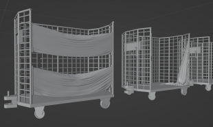
These BRUTEs illustrate what Blender can do. The metalwork will be easy enough in a CAD program, but the canvas sides not so much. Blender has this capability built-in, and these took me about three hours to design.
Blender is available for Windows, Mac and Linux. You can very easily export to an STL format file.
However, as it is a powerful, professional software tool, it is not as straightforward as some alternatives – though Fusion 360 will undoubtedly be just as complicated. Hence, this article.
CAD-based programs seem to be more orientated to taking an engineering drawing and converting that is to 3d. It much more encourages you to use exact measurements – which is generally a good thing. Fusion 360 tends to coerce you into good practices like this, and naming components and organising projects. It is designed for teams of engineers. However, it is more 2d based, perhaps because engineers are used to working from paper designs. In Fusion 360 you will be adding rectangles and circles to your model, modifying them, and then turning them into 3d components. In Blender you will be adding 3d components directly – cubes, cylinders, spheres, cones, etc. I suspect that whatever one package can do, others will adopt too, and the difference is in the approach they can take.
Terms
Vertex (plural vertices): A corner on a 3d object is a vertex, though a vertex can also be in the middle of a side. It is a point that edges run to and from. A box has eight vertices.
Edge: An edge is a straight line from one vertex to another; edges combine to make the sides of a face. A box has twelve edges.
Face: A side of a 3D object. A box has six faces. Faces can be curved, but I like to keep them flat. Behind the scenes, a face is made up of a number of triangles (often called polygons or polys); this is how all 3D models are composed in computers. In some applications it is vital to keep the polygon count as low as possible, but that is not an issue for 3D printing.
Mesh: A mesh is a set of connected vertices, edges and faces. For 3d printing, a mesh is the same as an object, but more generally an object includes materials and other things as well as the mesh.
There is a page here that has the clearance dimensions of the prototype. This page has the N gauge standards, this for OO and this for O gauge. This one has pretty much all gauges.
Getting started
Download from here:
https://www.blender.org/download/
The web page should detect what system you are using and offer the best version for you. Install it and you are good-to-go!
Note that you will need a fair-quality computer to run Blender (or any of the alternatives). A basic laptop may not be enough, and a tablet definitely will not. The most important requirement is probably a graphics card with 2 Gb RAM, with 8 Gb recommended.
First look
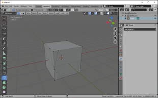
Fire up blender and you should see this:
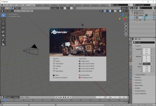
Click “general” to get past the splash screen; it will disappear, revealing a cube! Your first Blender object.
Let us take a few moments to look at the interface, as there is a lot there.
The Menu Bar
We will start with the menu bar. The only important one is the File menu, where you will find the usual New, Open, Save and Save as. You should also see Export, with an STL option.
To the right of the menus are various tabs that switch between different workspaces. A workspace is really just an arrangement of views, and for 3d modelling, the default “Layout” one is ideal (though the “Modelling” is not much different).
At the far right there are more options, but nothing for us to worry about.
The Status Bar
Across the bottom of the screen in the status bar; frankly not that useful to us.
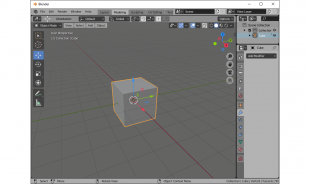
The Main Area
In the “Layout” workspace, the main area is divided into four areas, or screens. Top right is the scene hierarchy – a list of components of the scene and how they depend on each other; not generally useful, but you can access collections here, which we will look at later.
Below that is the Properties screen. This is important, and we will use this a lot later.
At the bottom is a narrow screen relating to animation – no use to us. Finally we come to the big screen with a cube in the middle, the 3d viewport.
Each of these areas has a button at the top left; click on it and you can change the editor type. That is generally not a good idea, but in case you do so by accident, you want the main view to be “3D viewport”, top right to be “Outliner” and bottom right to be “Properties”.
The 3D viewport
The 3D viewport has six modes, two of interest to us – “Object mode” and “Edit mode” – though Sculpt mode can be useful occasionally.
Your model will be made up of several different components, or objects as Blender calls them. Use “Object mode” to create and arrange the objects of the model, and use “Edit mode” to edit a specific object. You can use the [TAB] key to flip between the two. Try it now (you may need to click on the cube to get it to work – you need an object selected to go into “Editor mode”). The scene hardly changes, but some of the options do, in particular the toolbar down the left side.
We will be using many of those tools. Be aware that some of the buttons on the tool bar have a little triangle, at the bottom right. That indicates more options are available; click and hold on the button to have them appear. I mention this mainly so you know how to get back if you did this by mistake (it happened to me!).
The 3d World
Looking now at the actual 3D world, there are four things visible. Centre of the screen is the cube. A little way above is a large black dot with smaller dots around it; this is a light source. To the left is a pyramid; this is a camera. Both the light source and the camera can be deleted (just click the object, and press [DEL]). Spreading to the horizon is the X-Y grid, or “floor”.
X, Y and Z?
Computers use Cartesian co-ordinates to define the position of everything. That means every vertex (i.e., corner of an object), has a location defined by how far along the X-axis it it, how far along the Y-axis and how high up the Z-axis.
This is a very important concept, but hopefully will become clearer as we use Blender.
Navigating
Let’s have a fly around the 3D space! And I do encourage you to try out these features, rather than just reading about them.
Make sure the cube is selected. Hold down the middle mouse button (MMB), and move the mouse; you will rotate around – or orbit – the selected object.
Hold [SHIFT], and then hold down the MMB, and move the mouse; now you are panning. Alternatively, click the hand on the right side of the 3d viewport, and drag.
Hold [CTRL]-[SHIFT], and then hold down the MMB, and move the mouse; now you are zooming in and out. Alternatively, click the magnifying glass on the right, and drag. You can also spin the wheel of the MMB; this is more convenient, but a little more limited.
Use [ALT]-Z to toggle X-ray mode. In X-ray mode all the faces are transparent.
If you get lost…
It is a big world, and you can find yourself lost in the middle of nowhere, with no clue what direction your model is. Select an object from the scene hierarchy, top right, and then press the dot button on the number pad (at the bottom-right of the keyboard, may also be labelled “DEL”) , and you will get taken directly to that object. This is also useful to try if zooming seems to be very slow; it seems to reset something.
Also try hitting the HOME key, which should re-centre the view.
Orthographic views
Sometimes you want to see your model without perspective – very useful when trying to get things lined up. Top right of the 3d viewport you will see six coloured balls, three labelled ‘x’, ‘y’ and ‘z’. If you orbit the cube again, you will see these move too – they indicate the direction of each axis.
However, they can also be used to control the view. Click on the ‘z’ ball, and you will be looking down the z axis – the plan view. Click ‘x’ or ‘y’ to see a side elevation; click again to see from the other side.
To go back to perspective view, just orbit the object again with the MMB.
Selecting
In “Object mode”, you can only select whole objects.
In “Edit mode”, you can select vertices, edges or faces – but only on the object (or objects) you previously selected while in “Object mode”. To change between vertices, edges or faces click the appropriate button just to the right of where it says “Edit mode” – or use the ‘1’, ‘2’ or ‘3’ key.
In either mode…
Left click on something to select it; doing so will unselect anything else currently selected.
Hold [SHIFT] while clicking to select something whilst keeping the old selection. In object mode, the last object you click will be the master object, and will be highlighted a different colour. Sometimes this will be important.
You can drag the mouse to select a number of objects/vertices/edges/faces. For edit mode, if you are in X-ray mode, you will get the things at the back of the model, but otherwise you will only get the things you can see. However, in object mode you get the lot either way!
If you click the “Select box” button (top of the toolbar), you can also hold down [CTRL] and drag with the right mouse button to lasso select.
If you want to select all edges around a face, go into “Face select”, click on the face, and then go to “Edge select” – now all the edges are selected. Works for vertices too!
I suggest you have a play around to get a feel for how it works.
Object Mode
Object mode is used for creating new objects that will make up the model, and basic transformations of those objects.
Adding new objects
Stuff is complicated, and your model will undoubtedly be composed of numerous component objects. Blender has a number of options built in – called “primitives” – that you can add and modify as you require. Simply click “Add” (a little to the right of where it says “Object mode”, then “Mesh” and then the primitive you want.
The important ones are cube and cylinder, and to a lesser extend cone and UV sphere. These are the ones you will be using most.
When you create an item, a box will appear with its name, bottom left of the screen. Click the little triangle, and it will give more details – the actual numbers relating to your new item. This gives you the chance to modify it, but as before you need to do it before you do anything else, or you miss the chance.
How many sides does a cylinder have?
In particular, you may want to change the number of sides for a cylinder, cone or sphere. Computers cannot cope with curves; they fake it. A cylinder is really a prism with, by default in Blender, 32 sides around the supposedly curved surface. And when you 3D print it, it is going to look like a prism, not a cylinder. For video games, artists need to keep the model simple so it does not slow down the game, but for 3d printing, that is not an issue, so you need to think about increasing that for most cylinders. I work in N gauge; I think 128 is fine for a tank on a tank wagon. For small diameter cylinders, say for pipework and handrails, 32 sides should be fine. For a section of a cylinder, say the arch of a bridge, you might want to go up to 512.
Conversely, if you want an octagonal prism, set the sides to 8.
Note that spheres have two values that should be adjusted; segments and rings; rings should be half the value for segments.
Note: You cannot change the number of sides later! Pretty much everything else can be modified later, but not this. Get it right now.
Transformations
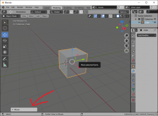
Make sure you are in “Object mode”, and click on the cube. Click the third button down on the left side, “Move”. Arrows appear on the cube. Click an arrow to move the cube along that axis. For example, click the blue arrow, and the cube will move up and down. There are also squares – click and drag the blue square and the cube will move around, but NOT up and down. You can also drag inside the white circle to move freely.
Click the fourth button, “Rotate”. Now there is a blue ring; dragging that will rotate the cube around the z-axis. With the fifth button, you can enlarge and shrink the cube. You can experiment for yourself to see how that works. The sixth button allows you do all three; move, rotate and resize!
When you do one of these transformations, a little box will appear bottom left, saying what you did – just as we saw when creating objects. You can type the numbers in the box to make them exact; if you want the cube to be exactly twice the size, type 2 in each of the three textboxes. Note that it is relative to whatever it was before. Also, you have to do it immediately, or the box disappears. Be aware that it resets with every operation.
An alternative approach is to do the transformations all through the numbers (but note that if you have multiple objects, doing it this way will only affect one of them). Make sure the cube is selected, and look at the properties – the screen to the right of 3d viewport, at the bottom. Make sure the seventh icon is selected “Object properties” – a square with funny corners (above a spanner). You will see the results of all those translations you just did.
To get back to the plain cube, just type 0 into all the location and rotation boxes, and 1 into the scale boxes.
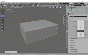
If you want a box that is exactly 4 mm by 6 mm by 2 mm, the best way is to type in those numbers, and it will be exact. Note that the default cube is 2 units on each side, so in fact you want 2, 3, and 1 in the scale boxes. Careful design of models, and keeping to round numbers as much as possible can very much help to keep your model neat, without unwanted gaps where bits do not quite meet, and ensure it turns out to be the right size.
Duplicating
To duplicate an existing object, select it, and do [SHIFT]-D. I do this a lot as I find it faster than going through the Add – Mesh menu. After the duplicate is created, you can move it around with the mouse. Press X, Y or Z to constrain it to only moving in that dimension.
That said, I find it best to press [ESC] to abort the move, and have it exactly where the original is, and then move it with the arrows as described before, as it is more controlled. Or to be even more precise, type the distance to be moved in the box, bottom left.
You can create a mirror image by creating a duplicate, then going to Object – Mirror (in Object mode). Note that there can be issues if you later apply scale or join this object to others – see here for details.
Joining and breaking apart
In “Object mode”, you can join two or more objects together to form a single object. This can be useful for keeping things together, but be aware that once done it is not readily reversed.
Select all the objects you want to join, and do [CTRL]-J.
Joining needs one object to be the master – the other objects are joining this object. You may notice one object is highlighted a different colour when several are selected. If join fails, [SHIFT] -click on one of the objects to make that the master, and try again.
Before doing a join, you should first do Object – Apply – Scale to any object you have mirrored, and also apply any modifiers (see below), so the components are correctly included in the mesh.
To break one object into two, go into “Edit mode”. Select all the vertices or edges or faces of the section you want to split off. Then press ‘P’ and select “Selection”.
An alternative approach to breaking up an object is to duplicate it, and in one copy delete one set of vertices and in the other delete the other set. This is a better approach if both parts share some vertices.
Object Mode: Modifiers
Blender has a large number of modifiers, though only a few are likely to be of use in this application.
A modifier is an operation that changes the object according to a set of rules into a somewhat different object. You might have a wall that you want to bend round a curve, or a brick that you want to repeat twenty times. Both of these can be done with modifiers.
Modifiers are applied using the Properties screen, bottom right. Ensure you have the spanner selected. Click on your object, then click “Add Modifier” and select the modifier you want to apply, then adjust any relevant parameters. Some require another object; click the eye-dropper icon, and then the other object.
When everything is right, you can click the apply button to permanently apply the modification. This is optional, however, and there may be times you prefer not to. That said, be aware that some operations, for example joining two objects together, will erase any modifiers that have not been applied.
Array
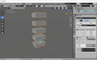
One of the simplest modifiers is Array – it simply repeats the object so many times. Change the numbers to have it repeat along a different axis, and with different spacings. Values of 1,0,0 will have the object repeat along the x-axis with no spacing, while 0,0,2 will have it repeat vertically along the z-axis, with a space equal to the height of the object between each one, as seen below.
This is a situation where you might not want to hit apply, so you can come back later to adjust.
Worth mentioning at this point that the scale and rotation you set in the Properties screen are transformations that get applied after these modifiers. Usually this is of no concern, but with array, you may find it does not work as you might expect. The trick is to go Object – Apply – Scale and Object – Apply – Scale before hand to get them set in stone. Now if you use “Constant Offset” rather than “Relative Offset” you can type in numbers and it will behave as you would expect. A value of 2 in the x field will have it repeat every 2 units.
Boolean
I think this is the most useful, as you can use it to punch a hole though anything. Let us suppose you have a box, and you want a round hole in it. Create a cylinder that is the width of the hole, and position it where you want the hole. Make sure it is longer than the box so it extends beyond where the hole will be.
Now select the box, and create a Boolean modifier. In the set up, click the eye-dropper, then click the cylinder. You should also check it is set to difference.
At this point the box has a hole in it, but the hole will move dynamically if you move the cylinder.
For this modifier, you may want to click “Apply”, so the change is set in stone. Then you can remove the cylinder, to reveal the hole. If you leave the cylinder there and export the whole model, the cylinder will be part of the model, so there will be no hole! One approach here is to move the cylinder to a different collection (I call it “cutters”), which you can then hide, when exporting; collections are discussed more later.
The Boolean operator can fail if the other object has complicated geometry. It is generally better to do a series of operations with simple objects rather than just one with a complicated object.
Mirror
The mirror modifier creates a mirror image of the object. the mirror image will update as you modify the original until you click Apply.
This is a great way to create a symmetrical object; you just do one side of it, and Blender does the rest for you. You do need to work along the axis, but you can create the part away from where it will end up, get it just right, then click Apply, and moving where you want.
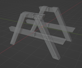
In the image below, the framework for a picnic table, the parts outlined are a single object; it is mirrored in both X and Y to give the complete thing.
Curve and Simple Deform
Curve works much like Boolean, as it again requires another object, in this case a circle or curve. As before select your object, add the modifier, then use the eye-dropper to select the second object.
In my experience, this can take some fiddling to get the amount of curve right. Remember you can modify the circle/curve object, and that will change the effect as long as you have not yet clicked “Apply”. Also make sure your object is not inside out – that the surface on the outside of the curve is the one it should be.
The window of the shop below was done using this technique.

It is a good idea to apply any scale and rotate before using this.
Sometimes curve does not work (and I do not know why!). In that case, try “Simple deform”, in “Bend” mode. You can choose which axis to curve round, and the angle. If it is curving the wrong way, try a negative angle. It might also be worth copy-and-pasting your object to a new file, and trying to get the curve modifier to work there, and if it does, apply it and copy-and-paste back.
Edit Mode
In “Edit mode” you can do the same Move, Rotate and Resize operations that you can do in “Object Mode”, but here you are just doing it to part of the object – the vertices/edges/faces you have selected.
I find the orthogonal views can be very useful in “Edit mode”, as you can box select all the vertices along one side in one go. But remember to turn X-Ray mode on ([ALT]-Z) to get the ones at the back too.
It can also be useful to use the forward slash key on the number pad to toggle the visibility of the rest of the world.
To quickly jump from one object to another in Edit Mode, point your mouse at the other object, and do [ALT]-Q.
It is sometimes useful to use “local” orientation, rather than global, if your object has been rotated. Top middle of the screen, click the little down arrow right of “Global”, and select local. The movement axes are now aligned to the orientation of the object. Note that if you try to move a bunch of objects while in local orientation, each will head off in its own direction. You will see a lot of red lines indicating directions when you do this.
Subdivide
To add a new vertex along an existing edge, select the edge, then right click and click “Subdivide”. You can then move that new vertex to wherever you want.
When you do subdivide, the little dialogue panel appears bottom right, and you can set it to add as many vertices along the edge as you want.
Select two parallel edges. Now when you subdivide new edges will appear between the new nodes.
The Knife Tool
The knife tool is not necessary to cut bits off; it creates new edges within a face. That said, we will use it to cut a corner off the cube. Make sure the cube is selected, go into “Edit Mode”, and select the knife tool.
We will cut off the corner pointing towards you (the knife tool is difficult to use on faces that are behind something). Click on one edge, then the next and the next going round the corner, then back on the starting point. Press [RETURN] to confirm (or [ESC] to abort, and start again).
Now go to the “Select box” tool. Click on the vertex at the corner of the cube, and press [DELETE], and when the menu comes up, select vertices. The corner has gone!
This does, however, reveal that your cube is hollow! If you try to print this, the software will try to print a box with sides of zero thickness, and nothing will come out. This is an issue you need to keep in mind with all operations. An object with a hole in it will not print.
We need to fill the hole. Select the three vertices we created with the knife, and press the ‘F’ key. A new face is created; the hole is gone. The ‘F’ key can also be used to create a new edge, if only two vertices are selected.
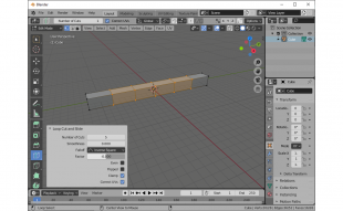
The bevel tool
The bevel tool effectively sands off an edge if you have an edge selected, or all the edges around a face if you have a face selected. It can get confused with complicated faces, or just try to go too far, but is very useful. You can do [CTRL]-B as a shortcut.
The dialog box at the bottom left has a segments box, put a number, say 16, in here to have a gentle curve to the bevel.
This is another time when it is a good idea to apply the object scale before hand.
By default, bevel just gives a flat edge, but if you click on custom at the bottom, and have a high number of segments, you can have any weird shape you want.
The loop tool
The loop tool is similar to the knife, in that it creates new edges within your object, but it does so in a loop all the way around it (as long as it is not too complicated). If you are not sure what the means, try it and see what happens!
The properties box at the bottom left will allow you to create as many loops as you want in one go. I have added 5 in the image below.
The Extrude Tool
Select one face, press E, then drag. The face will be pulled out, and new faces created around it to join it to the rest of the model.
This is a really useful, but not easy to explain, so I suggest you try it for yourself. Once you see it in action, it will make sense.
The spin tool
This is really useful for making fancy columns, vases or anything with cylindrical symmetry, but takes some work. It is like extrude, but in a circle, rather than a straight line, which does make it rather more complicated…
The basic operation is to select a face, select the tool (looks like a cake with a slice cut out), and drag. It will try to guess which way to curve it, but usually gets it wrong! Just go to the usual properties panel, bottom left, and change it as required.
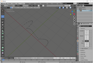
Let’s make something more complicated! This technique can be used to make a vase, column or similar.
You need to first create the outline of the object along one side. Make sure it is flat, with every vertex at the same Z value, and drawing along the X-axis. One way is to make it out of Bezier curves. Join them together ([CTRL]-J), convert to meshes (object menu), and merge vertices together to make a continuous shape.
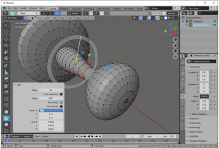
Select every vertex, then click the spin tool. It defaults to spinning round some random axis; do that quickly to get the usual dialogue box to appear, just drag somewhere along the curve that appears.
Now we can fill in the details to get what we want. In the image, I did 32 steps; that is a bare minimum, for something large four times that will be required. You can see this does not look smooth. As with adding cylinders, you need to get this right now – you cannot change it later.
The angle needs to be 360, a full circle. The centre is 0,0,0, the axis is 1,0,0 (around the X axis).
Aligning points
There is a trick you can use to align points with each other – resize them!
Select all the points you want to align, then use the resize tool to shrink them along one axis. In the dialog panel, type zero into box for that axis. Now they are all aligned.
Sculpt Mode
Introduction
Sculpt Mode is great for more organic models – things with curves, rather than straight lines. When making buildings or roll stock there is not much need to it, but you could use it if you want to model the face of Thomas the Tank Engine.
It can be selected from the same drop-down as Edit and Object Mode, top right, but I prefer to go to the Sculpt tab. As the name suggest allows you to sculpt a model, perhaps like an artist might sculpture a statue from rock or a potter from clay.
This is heading more into the artistic side of Blender, and I would guess is something you would not be able to do in the CAD-based software like Fusion360. It is something that requires quite a different skill set; it is not just knowing how to do it, you need the skill to apply it. I take the view that in N gauge I can do it good enough.
Sculpt Mode is general best done with “DynTopo”. DynTopo is short for Dynamic Topology, and when that is turned on, Blender will add new vertices/edges/faces to facilitate the operation. If you have a box, tell Blender you want a gouge cut out of it, Blender will first split the existing faces into smaller faces, and then will move the vertices to create the gouge. This process can create some very complicated models, and if you are creating models for a computer game, that could be a big problem, so “DynTopo” is off by default. You need to remember to turn it on every time.
Getting Going
To use Sculpt Mode, select an object, then go to the Sculpt tab. A big line of brushes will appear at the bottom, as well as some new tools on the left. Now click the “DynTopo” check box, top right. You are ready to start.
Brushes
There are a lot of brushes to choose from, and really you are going to need to experiment to get what they do. As a hint, the blue ones do add/subtract, the red do contrast (if you can work out what that means in this context), and yellow for transform. There are also some general brushes with no particular colour.
Across the top you should see further options that let you modify the brush, including the brush size.
Hints
Try downing down [Ctrl] while you use a brush; it should reverse the effect.
It will probably be a good idea to run the Smooth brush over your model; you can get some very spiky surfaces.
Remember you can do [Ctrl]-Z to Undo if you mess up.
Importing Images
You can import images as SVG. You can often find company logos in that format, or create your own in InkScape, for example. Import via the File menu. Select it, then go Object – Convert – Mesh to convert it to a normal object. You can then extrude it to give it depth, and put it on the side of your building or whatever.
You can also import plans and elevations to give you something to work to.
Hiding Things
It is often helpful to be able to hide the bits of your model you are not working on. Blender has several ways to do this. Note that all objects, whether hidden or not, will get exported, unless you tick “Exported selected only”, in which case only objects that are selected will be.
Press H to hide an object, or [SHFT]-H to hide every other object. Press [ALT]-H to bring them all back.
Press the / key to hide everything not currently selected, press it again to bring them back.
Collections
You can put objects into collections by selecting a group (or just one object) and pressing M. You will be offered a list of existing collections or you can create a new one by giving a suitable name. You will see the collection in the hierarchy, top right.
You can hide all the objects in a collection by clicking the eye to the right of the name in the hierarchy; the icon will change to a closed eye. In Object mode, pressing a number button will hide all other collections, so press 3 to hide every collection except the third.
You can also lock items in a collection. Click the filter funnel icon above the hierarchy, and click the little arrow, and now that arrow should appear by the eye. You can use that to make it so that objects in a collection cannot be selected.
Collections are very useful if your model is several parts. Put each part in its own collection. When you come to export, hide all the other collections, press ‘A’ to select all, and then when you export, tick the “Selection only” tick box.
You could keep meshes that are used for sizing or as building blocks in another collection, and meshes used to cut bits out with the Boolean modifier is a further collection (the mesh will still do its thing even when hidden).
Tips
Select a suitable prototype
The first trick is to model something you can model. Something fairly simple. Things that are repeated are great for computers – you create the first one, and copy-and-paste! Buildings with rows of identical windows are a good starting project.
Stuff is big! A small church in N gauge will be 15 to 17 cm long. Boots in Preston would be about 13 cm wide, and 40 cm deep. The bus station would be 1.2 m long. I strongly suspect a lot of kits have been compressed to fit or they chose really tiny prototypes to model!
Brickwork is tricky. Brickwork where there are angles other than 90 degrees are significantly harder. Bricks on curves are much harder. Slate or tile rooves are worse, as they are already at an angle. Do not even think about doing a curved slate or tile roof.
Complex curves can be tricky too. The sleek lines of a modern car will be difficult, but do have the advantage you will realise that very early in the project.
First steps
Get the basic shape first, using nice round numbers – typed in – to ensure sections connect. If there is a line of symmetry ensure that is along one axis. Ensure you have the basic proportions right. Then hollow out, and do medium-level detail next.
One unit in blender is 1 mm in the printed model. I suggest you use the X-axis for the long side and the Y for the short just because you will then know which axis is which later.
Look at stuff! When you are out and about, look at buildings and whatever, and think about how they could be broken up into component objects in Blender. Also, pay attention to the details, and think how they could be done. In particular, look at how different things fit together. You are probably familiar with Flemish bond brickwork, where alternate bricks are end on, but what happens at corners?
Going forward
Work defensively! That means save often, and occasionally save as a different file – especially if trying something new. My experience is the Blender is pretty stable, but you really do not want to have to redo hours of work if something does happen and it crashes.
Remember you can do [CTRL]-Z to undo, but you can only go back in time so far (32 steps by default, but you can increase that if your computer will support it in Edit – Preferences – System). Undo steps include selecting and unselecting, and you will hit the undo limit fairly fast!
Blender does keep a back-up of your previous save, with a .blend1 extension.
If something is not quite right, stop now and sort it. It is far better to do that, than to keep going, and hours (or days) later realise you are not going to be happy with the end result.
Creation for a 3d print
You do need to keep in mind that ultimately you want to 3d print your model.
The overall size of each component of your model can be no bigger than the print volume of your printer – and possibly rather less, depending on orientation.
Ensure everything is hollow, but has thickness. A cube with one face missing is hollow, but the walls have zero thickness!
Anything more than 5 mm thick should be hollow, and have openings connecting it to the open world. More specifically, you need to ensure air and resin can flow in and out whilst the model is being printed.
Avoid large flat (i.e., horizontal) areas; the resin is viscose and during printing resin will not have time to flow out from behind it, and the weight is liable to pull it off the supports. The way around this is to change the orientation when you print, but be aware of that when you design.
Walls should by 1 to 2 mm thick, depending on how strong they need to be. Free standing details should be no thinner than 0.2 mm, but detail on a surface can be as small as 0.1 mm. That said, you may need to experiment a bit, and see what works on your printer.
Sometimes it a good idea to break models up into parts (if the model is bigger than your print area, then it is forced on you!). Knowing what should be a separate part is a skill unto itself, but as an example, for a station building, I did the iron work supporting the canopy as one part that was printed upside down, the canopy roof was another part, the main roof another part and the rest was a fourth part. This minimised the number of supports required when printing, which saves resin and makes removing them easier.
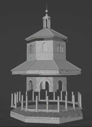
This market cross I had to break up into six parts, and the large flat base had to be printed vertically.
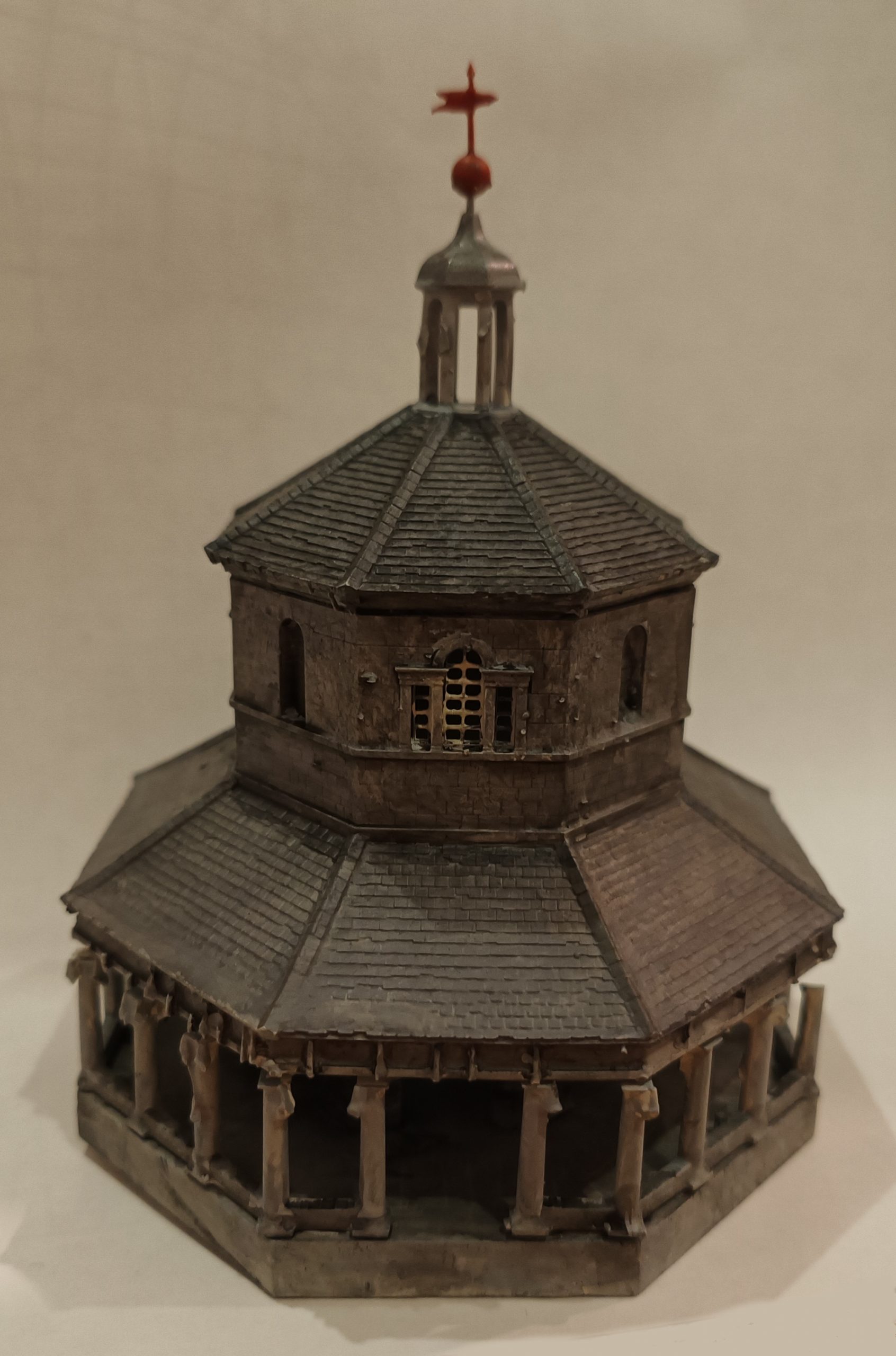
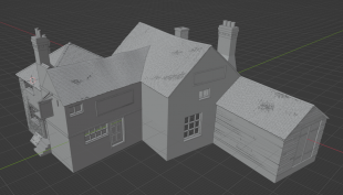
On the other hand, buildings with sloping rooves tend to work well as one piece, even when fairly complicated. And conversely would be difficult to break up. This pub I printed as a single object.
Exporting
To export everything (including hidden items!) just do File – Export – STL, and give it a suitable name.
To just export part of the creation, select it, do File – Export – STL, and tick the “Export selected only” checkbox before giving it a suitable name.
There is a program called Microsoft 3D Builder, which is free to download. It is a good idea to load your STL file up in this and let it do any repairs it thinks necessary before trying to print. Once installed, you should be able to double-click the STL file to start the program. Click import at the top left, then, if it says there are issues, click repair at the bottom right. It will then do whatever it thinks necessary. You then need to save the file, as an STL again. It is important to flag this as the repaired version so you know which is which later; I save to a sub-folder called “repaired”. I know anything in that folder is okay to print. Alternatively, you could append “repaired” to the file name.
Your model is now ready to be imported into your slicing software.
My printing workflow is described in some detail here (off-site).
Useful shortcuts
These are worth knowing if only because you can hit them by accident and wonder what you have done and how to reverse it.
[TAB] to toggle edit mode and object mode
[ALT]-Z to toggle X-ray view
[SHIFT]-D to duplicate the selected object
F to create a new face joining the selected vertices
[CTRL]-Z to undo (does not seem to work when using the knife tool, but go into something else, and you can go back as normal)
[SHFT]-[CTRL]-Z to redo something you just undid.
[CTRL]-J to join objects together
P to split an object (you also need to click “selection”)
H to hide selected
[SHIFT]-H to hide all except selected
[ALT]-H to unhide all hidden items
[SHIFT]-A to add an object
[DEL] or X to delete
B to box select (does not look the same as using the tool but the effect is the same)
[SHFT]-[TAB] to toggle snap to grid
[HOME] to centre the view
And if it goes wrong…
Blender has a lot of shortcuts, which means pressing the wrong button at the wrong time can lead to issues. Besides the ones above:
If parts of your model have disappeared, they could be hidden with the ‘H’ shortcut above, but they can also be hidden in the Outliner (the screen top right). Pressing a number in “Object mode” can do this. To revert, make sure every item in the list has an open eye icon to the right of it.
The ‘T’ and ‘N’ keys make bits of your interface appear and disappear, but there are other more esoteric actions. The ultimate way to recover the interface is to do [ctrl]-S to save your model, and close down Blender. Then start it up again, going into the default empty file. From here, go File – Open, and navigate to your file. select your file, but before opening it, click the cog wheel, top right, and untick “Load UI”.
You can drag from the edge of a window and Blender will create a new window for you. This is rarely useful, and it is not at all obvious how to get rid of the excess windows. Suppose you have two windows you want to merge into one, sat side by side. Move the mouse cursor to the top left or bottom left corner of the window on the right, and you will see the cursor changes to a cross. Left click whilst near the corner – so the cursor is astill cross – but still inside the right window. Now drag to the left, into the other window; the cursor will change to a left chevron. When you release, the left window will disappear, and the right window will have expanded to fill the space. The same principle applies for vertically stacked windows.