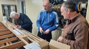
Another meeting last night, and “Kitchen Mike” was again there to help the discussion with regards to baseboards. He brought along some prototypes too.
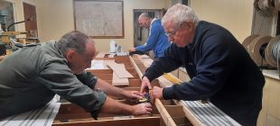
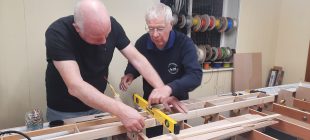
Baseboard construction
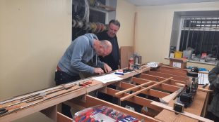
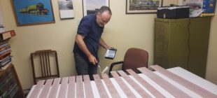
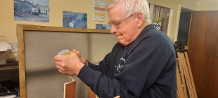
Mike had two “L” pieces about 8″ long, with an upright, showing how strong they are and well aligned.
The verticals are 12mm ply, nailed to 9 mm ply horizontal pieces. The upright, which will support the upper level track, was 18 mm, but would be 12 mm on the layout, and was both screwed and nailed. A spacer, again 12 mm, was then glued to the upright to bring it flush with the vertical. This does require a hole cut out of the horizontal for the upright to go through (vital for strength in the upright).
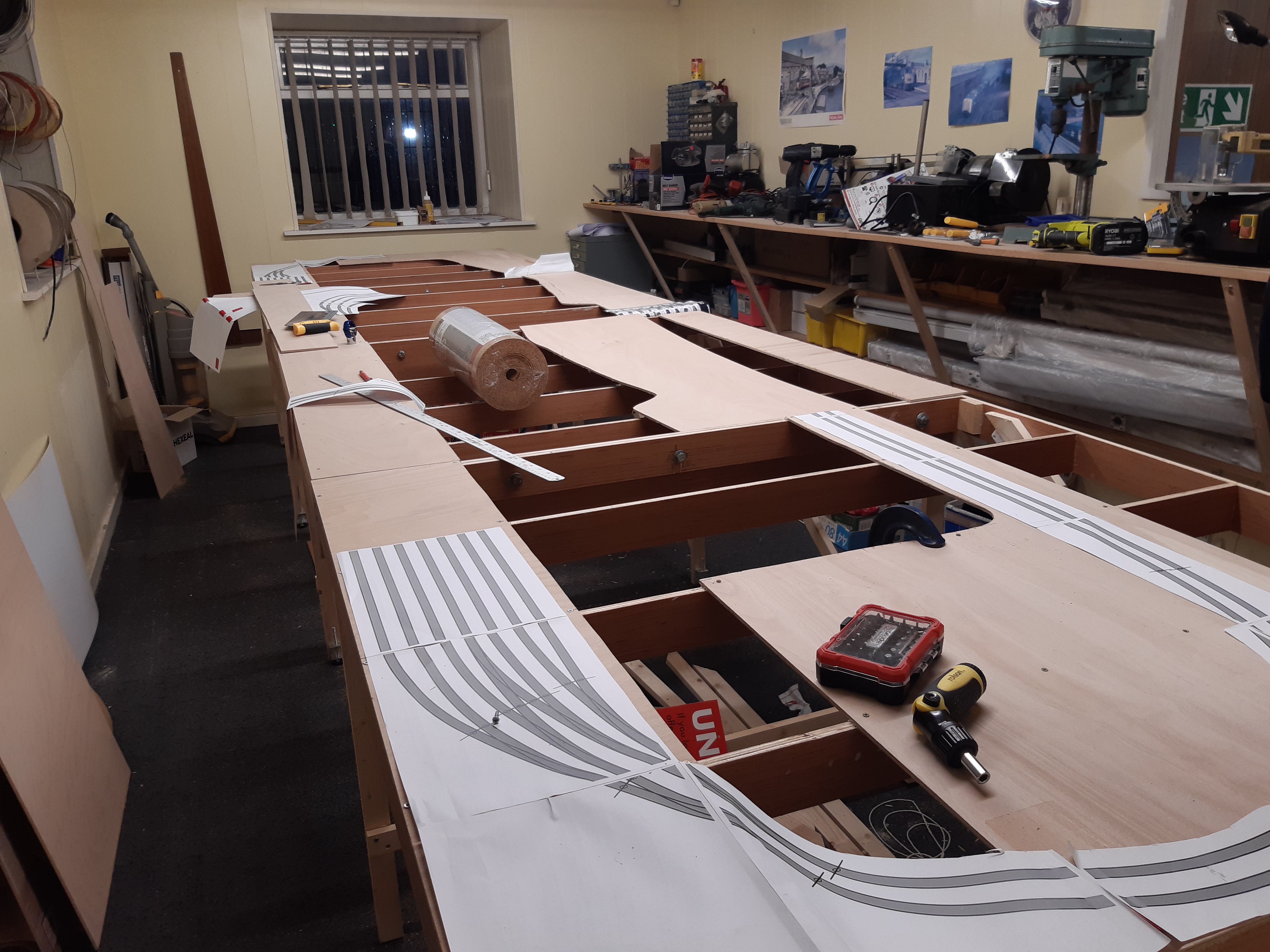
The baseboard would go on top of that, so resting on top of the horizontal in some places. It may be necessary to cut further holes in the horizontal for point motors (though the ones at the far right could be on top of the boards as they are in tunnels, accessed from the side).
Cross pieces would need the top corners removed to allow for the horizontals.
I will try to remember to get a photo on Wednesday and add it here.
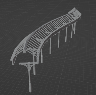
Splines
Another suggestion by Mike is to build a “spline roadbed”. We had been thinking of cutting the track beds out of ply, but that is very wasteful in wood, as most of the sheet is just discarded. An alternative, popular in the US but pretty much unheard of in the UK, is to use vertical boards! Each board is only about an inch high, and numerous are glued together to give the required width. The lamination means they keep their space. Spacers are also put in place to keep weight down.
This should mean that the number of supports required is much reduced, because it will be very solid.
This is the website Mike found:
http://www.windsormodelrailroadclub.com/archive/tips-spline.php
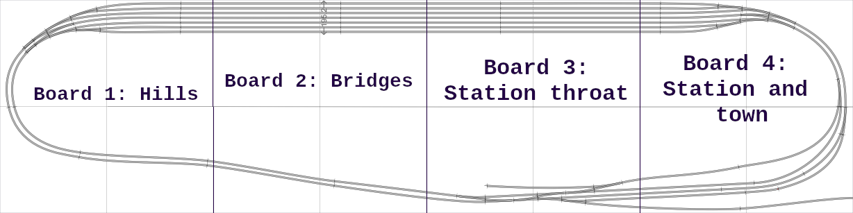
Do we use splines where the track is relatively straight? Certainly not for the viaduct.
Do we use splines on the lower level at the left? This would require cutting into the cross pieces, but I think would be the best way.
If you have a solid spline, 2″ across, 1″ deep, and a 90° arc of radius 12″, you are using about 37 cubic inches of wood. On the other hand, if you have a sheet of 6 mm ply and cut the trackbed from it you use about 40 cubic inches of wood. So in terms of wood usage, there is not much difference. Introducing spaces into the splines will help that.
Trolley
Previously someone had pointed out that not all exhibitions have double doors, and it may not be possible to get a 4′ by 4′ trolley inside a hall, and this engendered a discussion on a possible 2.5′ by 4′ trolley, with boards stored vertically. It was generally felt that we would stick to the 4′ by 4′ trolley idea, keeping the boards horizontal as much as possibly during transit. We would select exhibitions with good access (which is the vast majority).
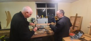
Mike brought along some bed fittings attached to two short lengths or wood. One slotted into the other to provide a very secure fit. He suggested the trolley could be constructed so the four sides come apart in this way, splitting down the L of each leg. During later discussion we realised this was not really what we wanted, and again the original plan was the best.
We agreed we need the biggest wheels we can practically find, 5″ if available.
It was noted that if we do mess up the trolley, it would not be that bad if it had to be re-built.
Also…
Mike said that January is often (but not always) a quiet time for him, so would like to have the details by then.
The next meeting will be on the 11th, as the last available Monday of the year.